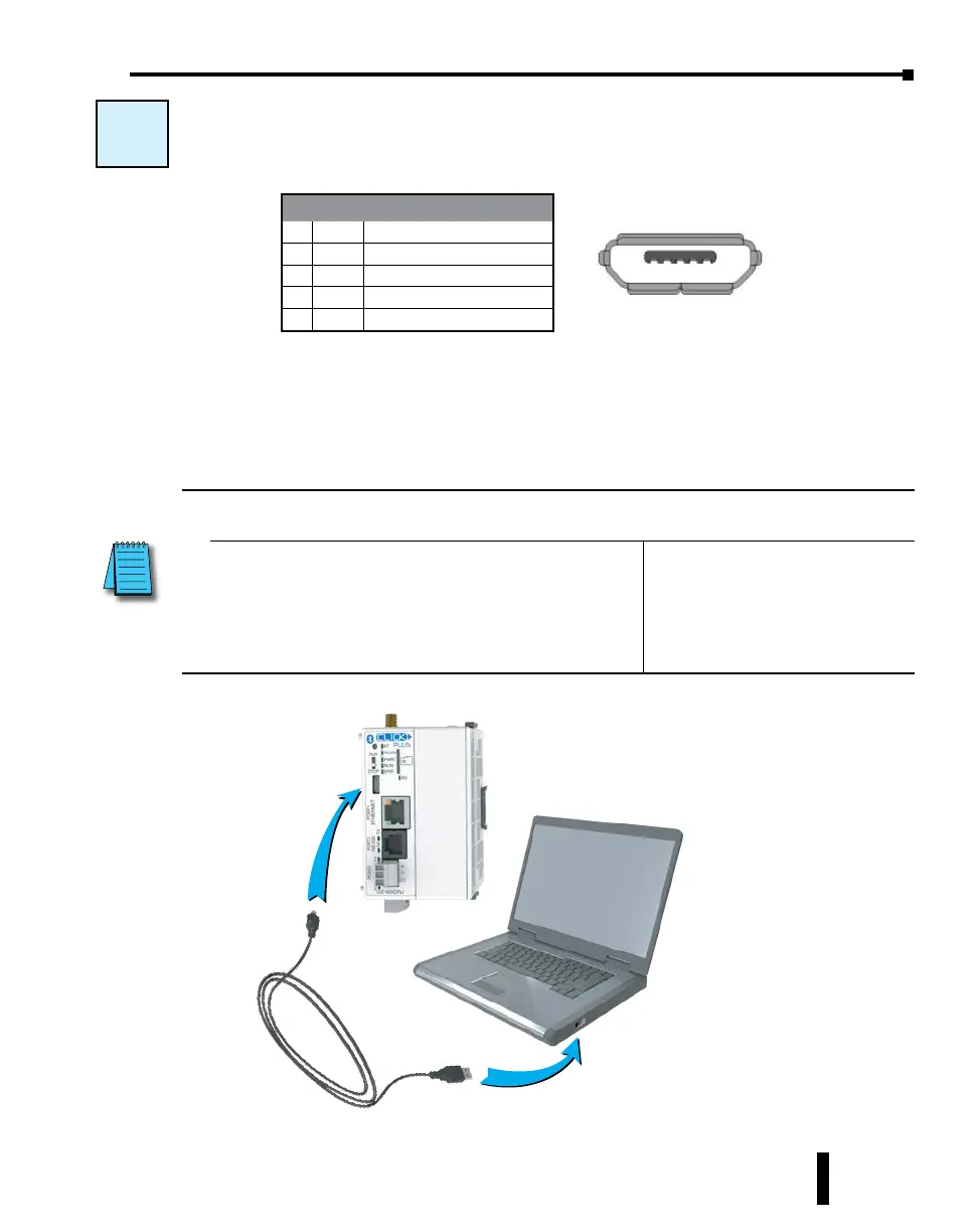
W-1: USB Port Wiring
USB Port wiring pinout is shown below.
Wiring Strategy
Connect any CLICK PLUS CPU to a USB A port on a Windows PC, using cable
USB-CBL-AMICB6 or equivalent.
W-1
USB Port Pin Descriptions
1 VBUS 5V Power supply in
2 D- Differential signal -
3 D+ Differential signal +
4 NC Not connected (ID not used)
5 GND Ground
1 - 5
USB Cable
ADC Part #
USB-CBL-AMICB6
PC with
USB A Port
CLICK Plus
PLC
NOTE: The CLICK PLUS CPU can be supplied 5VDC power from a PC over the USB port when no
24VDC power is applied, with the following capabilities and restrictions
Available:
• Programming over Port 1, Port 2, and Port 3
• Firmware update
• CLICK Factory Default and CLICK Project Loader Tools
• Modbus Server/Slave over Port 1, Port 2, and Port 3
• Option Slot module can be identified in software
Not Available:
• RUN mode is disabled
• WLAN and Bluetooth are disabled
• Access to the microSD Card from
software is disabled
CLICK PLUS PLC Hardware User Manual, 1st Edition, Rev. B – C2-USER-M
4-11
Chapter 4: PLC Communications