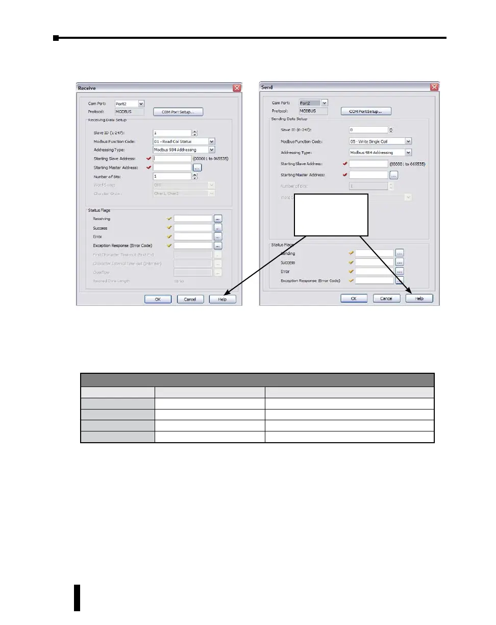
When you open the Receive or Send instruction in the Modbus mode, their windows should
look like this. For the explanation of each setup parameter, please click the Help button on
the bottom right.
Com Port Status Indicators
The CLICK PLC has the following System Control Relays to indicate the status of the Com
Ports. If monitoring these bits in ladder, they should be monitored at a ladder location prior
to the Receive or Send instructions for the port.
Click the Help button
to get detailed
information on this
setup window.
System Control Relays
Address Nickname Description
SC100 _Port_2_Ready_Flag On when Port 2 is ready.
SC101* _Port_2_Error_Flag On when Port 2 has a communication error.
SC102 _Port_3_Ready_Flag On when Port 3 is ready.
SC103* _Port_3_Error_Flag On when Port 3 has a communication error.
* Errors that will cause SC101 or SC103 error flag to turn on:
• Parity Error
• Frame Error
• Time Out
• CRC Error
• Modbus Exception Response
CLICK PLUS PLC Hardware User Manual, 1st Edition, Rev. B – C2-USER-M
4-32
Chapter 4: PLC Communications