A-56
BX Series
<MS-4>
Mounting and sensitivity adjustment
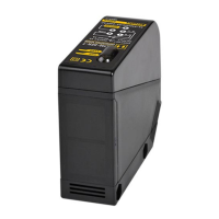
1. Supply the power to the photoelectric sensor, after
setting the emitter and the receiver facing each other.
2. Set the receiver in center of position in the middle of the
operation range of indicator adjusting the receiver or the
emitter right and left, up and down.
3. After adjustment, check the stability of operation putting
the object at the optical axis.
※
If the sensing target is translucent body or smaller
than ø15mm, it can be missed by sensor cause light
penetrate it.
※
Sensitivity adjustment: Refer to the diffuse reflective
type’s.
1. The sensitivity should be adjusted depending on a
sensing target or mounting place.
2. Set the target at a position to be detected by the beam,
then turn the adjustment VR until position
ⓐ
where the
operation indicator(yellow LED) turns ON and the self-
diagnosis indicator(green LED) turns OFF from min.
position of the adjustment VR.
3. Take the target out of the sensing area, then turn the
adjustment VR until position
ⓑ
where the the operation
indicator (yellow LED) turns OFF and the self-diagnosis
indicator(green LED) turns ON. If the indicators do not
operate, max. position is
ⓑ
.
4. Set the adjustment VR at the center of two switching
position
ⓐ
,
ⓑ
.
※
Above sensitivity adjustment is for Light ON mode. If it
is for Dark ON mode, operation indicator(yellow LED)
operates opposite.
※
The sensing distance indicated on specification chart is
for 200×200mm of non-glossy white paper. Be sure that
it can be different by size, surface and gloss of target.
1. Supply the power to the photoelectric sensor, after
setting the photoelectric sensor and the reflector(MS-2)
in face to face.
2. Set the photoelectric sensor in the position which
indicator turns on, as adjusting the reflector or the
sensor right and left, up and down.
3. Fix both units tightly after checking that the unit detects
the target.
※
If using more than 2 photoelectric sensors in parallel,
the space between them should be more than 30cm.
※
If reflectance of target is higher than non-glossy white
paper, it might cause malfunction by reflection from
the target when the target is near to photoelectric sensor.
Therefore put enough space between the target and the
photoelectric sensor or the surface of the target should
be installed at angle of 30° to 45° against optical axis.
(When a sensing target with high reflectance near by,
photoelectric sensing with the polarizing filter should be
used.)
※
Sensitivity adjustment: Refer to the diffuse reflective type’s.
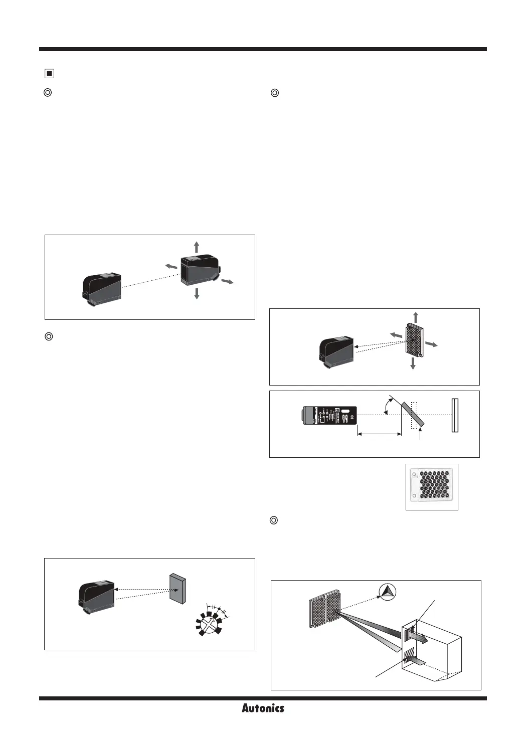
The light passed through the polarizing filter of the emitter
reaches to the MS-3 reflector converting as horizontal
direction. It reaches to the receiver element of polarizing
filter converting as vertical by the MS-3 reflector. Therefore,
this type can also detect reflective mirror.
※
If the mounting place is too narrow,
please use MS-4 instead of MS-2.
Adjust
Right/Left
Adjust Up/Down
Optical axis
Emitter
Receiver
Sensing
target
Optimal
position
MIN
MAX
Photoelectric
sensor
ⓐ
ⓑ
Vertical direction
polarizing filter
Horizontal direction
polarizingfilter
MS-3
Receiver
Emitter
Through-beam type
Retroreflective type
Diffuse reflective type
Retroreflective type(Built-in polarizing filter)
Adjust
Right/Left
Adjust Up/Down
Photoelectric
sensor
Reflector
(MS-2)
Optical axis
L
30° to 45°
Reflector
(MS-2)
Sensing
target
 Loading...