A-53
(A)
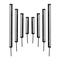
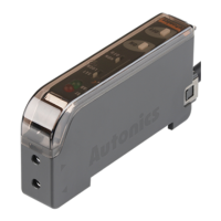
Photo
electric
sensor
(B)
Fiber
optic
sensor
(C)
Door/Area
sensor
(D)
Proximity
sensor
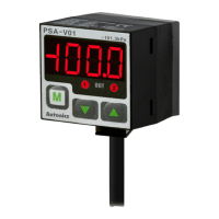
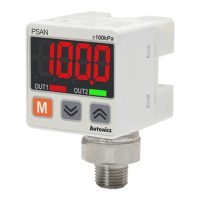
(E)
Pressure
sensor
(F)
Rotary
encoder
(G)
Connector/
Socket
(H)
Temp.
controller
(I)
SSR/
Power
controller
(J)
Counter
(K)
Timer
(L)
Panel
meter
(M)
Tacho/
Speed/ Pulse
meter
(N)
Display
unit
(O)
Sensor
controller
(P)
Switching
mode power
supply
(Q)
Stepper
motor&
Driver&Controller
(R)
Graphic/
Logic
panel
(S)
Field
network
device
(T)
Software
(U)
Other
Long Sensing, Amplier Built-in type with Universal voltage (terminal)
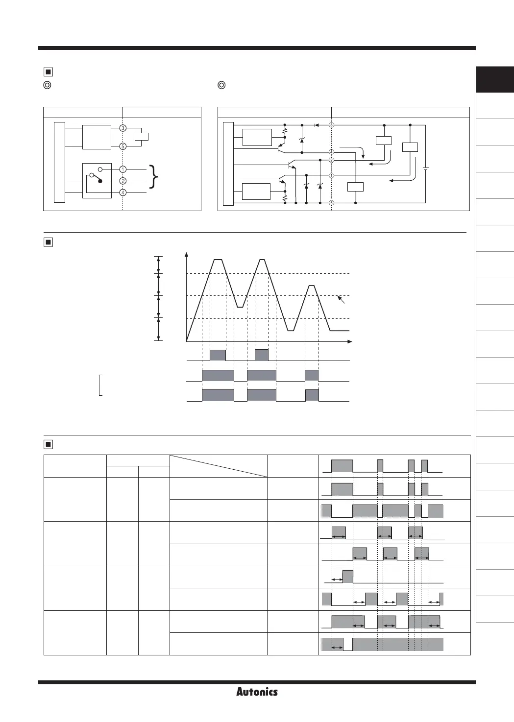
Photoelectric sensor circuit Connection
24-240VAC±10%
24-240VDC±10%
OUT
250VAC 3A
30VDC 3A
Output relay
N.O.
N.C.
COM
Universal
power
circuit
+
-
Power
Main circuit
Control output diagram
Operation timing diagram
Timer mode
※
T : Time set by the timer adjustment VR.
※
Conversion to another mode of timer modes is applied after a former mode is nished.
※
In case of product with the output protection device, if terminals of control output are short-circuited or overcurrent condition exists, the control
output will turn off due to protection circuit.
Photoelectric sensor circuit Connection
12-24VDC
±10%
Max. 200mA
Max. 200mA
Max. 50mA
Overcurrent
protection
Overcurrent
protection
Load
Load
Load
+
-
Main circuit
Free power type
(Relay contact output)
DC power type
(NPN/PNP open collector simultaneous output)
Timer mode
Switch position Received light
S1 S2 Interrupted light
Normal ON ON
Light ON
ON
OFF
Dark ON
ON
OFF
One-shot Delay ON OFF
Light ON
ON
OFF
Dark ON
ON
OFF
ON Delay OFF ON
Light ON
ON
OFF
Dark ON
ON
OFF
OFF Delay OFF OFF
Light ON
ON
OFF
Dark ON
ON
OFF
Operation mode
Status of light
T
T T
T T T
T
TTT
T T T
T
※
The waveforms of “Operation indicator” and “Transistor output” are for Light ON operation. They are opposite operation for Dark ON operation.
※
If the control output terminal is short-circuit or over current than the rated current flows in the unit, the sensor does not operate normally by
protection circuit.
Unstable operation area
Stable light OFF area
Transistor output
(Relay)
Light ON
operation
ON
OFF
ON
OFF
ON
OFF
Stable light ON area
Stability indicator(green LED)
&
Self-diagnosis output
Operation
level
Operation indicator
(orange LED)
High
Incident
light
level
Low
 Loading...