J-19
LCD Display Counter/Timer
(A)
Photoelectric
Sensors
(B)
Fiber
Optic
Sensors
(C)
Door/Area
Sensors
(D)
Proximity
Sensors
(E)
Pressure
Sensors
(F)
Rotary
Encoders
(G)
Connectors/
Connector Cables/
Sensor Distribution
Boxes/Sockets
(H)
Temperature
Controllers
(I)
SSRs / Power
Controllers
(J)
Counters
(K)
Timers
(L)
Panel
Meters
(M)
Tacho /
Speed / Pulse
Meters
(N)
Display
Units
(O)
Sensor
Controllers
(P)
Switching
Mode Power
Supplies
(Q)
Stepper Motors
& Drivers
& Controllers
(R)
Graphic/
Logic
Panels
(S)
Field
Network
Devices
(T)
Software
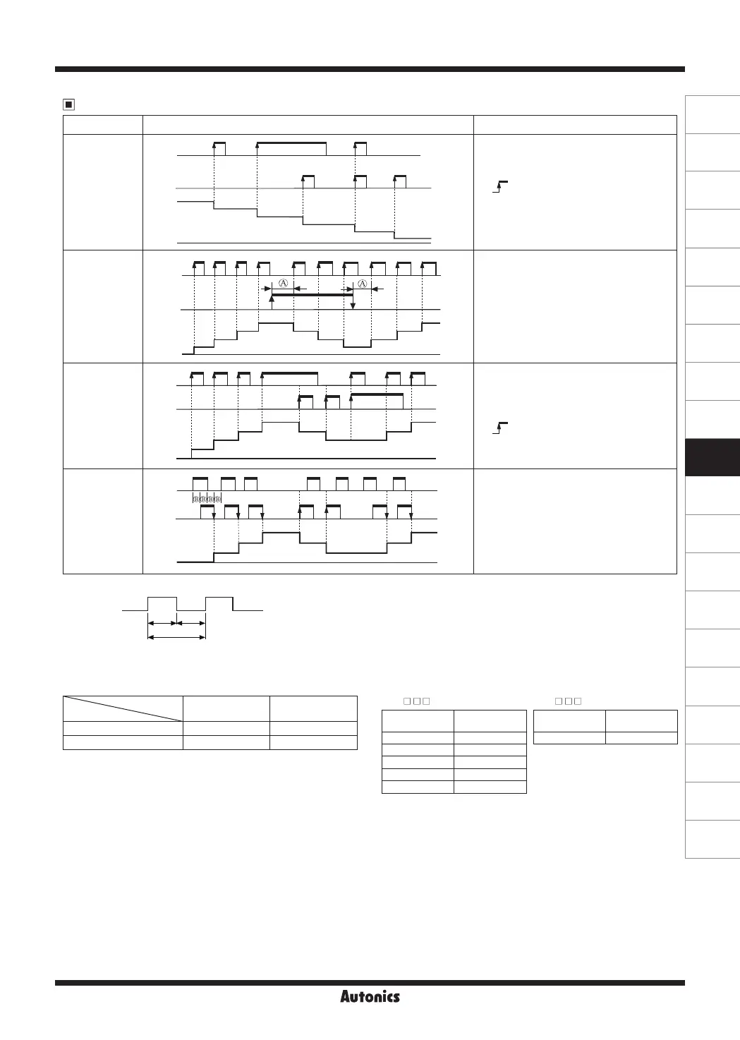
Input Operation Mode (Counter)
※
A: over min. signal width, B: over than 1/2 of min. signal width. If the signal is smaller than these width, it may cause counting error (±1).
※
T.on, T.off: Min. signal width
INA
(INB)
ON
T.on
T
T.off
ONOFF OFF
H
L
Input mode Counting chart Operation
Down-3
[
DN-3
]
INA
H
L
0
n
n-1
n-2
n-3
n-5
n-6
H
L
INB
Count
※
When INA or INB input signal is rising
( ) , it counts.
※
INA: Counting input
※
INB: Counting input
Up/
Down-A
[
UD-A
]
INA
H
L
0
1
2
3
4
3
2
1
2
3
4
H
L
INB
Count
※
INA: Counting input
INB: Counting command input
※
When INB is "L", counting command is up.
When INB is "H", counting command is
down.
Up/
Down-B
[
UD-B
]
INA
H
L
0
1
2
3
4
3
2 2
3
4
H
L
INB
Count
※
INA: Up counting input
INB: Down counting input
※
When INA and INB input signals are rising
( ) at the same time, it maintains
previous value.
Up/
Down-C
[
UD-C
]
INA
H
L
0
1
1
22
2
3
3
H
L
INB
Count
※
When connecting encoder output A, B
phase with counter input, INA, INB, set
input mode [
InM
] as phase different input
[
UD-C
] for counter operation.
※
The meaning of "H", "L"
Input method
Character
Voltage input
(PNP)
No-voltage input
(NPN)
H 5-30VDC Short
L 0-2VDC Open
[CX6 - ] [CX6 - F]
※
Min. signal width by counting speed
Counting
speed
Min. signal
width
1cps 500ms
30cps 16.7ms
300cps 1.67ms
1kcps 0.5ms
5kcps 0.1ms
Counting
speed
Min. signal
width
20cps 25ms
 Loading...