INSTRUCTION MANUAL
TEMPERATURE CONTROLLER
TC4 Series
※
1: Thermocouple L (IC) type, RTD Cu50Ω
At room temperature (23
℃
±5
℃
)
:
(PV ±0.5% or ±2
℃, select the
higher one) ±1digit
Out of room temperature range:
(PV ±0.5% or ±3
℃, select the
higher one) ±1digit
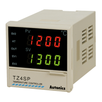
In case of TC4SP Series, ±1
℃
will be added.
※
2: The weight includes packaging. The weight in parentheses is for unit only.
※
Environment resistance is rated at no freezing or condensation.
TC4S/SP (48 48mm) Series
TC4Y (72 36mm) Series
Other Series
※
1:
In case of the AC voltage model, SSR drive output method (standard ON/OFF control, cycle control,
phase control) is available to select.
※
2:
It is unavailable for TC4SP, TC4Y.
※
3:
Sockets for TC4SP (PG-11, PS-11(N)) are sold separately.
Ordering Information
Specications
Unit Description
Input Sensor and Temperature Range [
IN-T
]
Installation
Dimensions
Connections
T C 4 S 1 4 R
Item
Setting type
Digit
Size
Sub output
Power supply
Control output
N
Indicator - Without control output
R
Relay output+SSR drive output
※
1
2
24VAC 50/60Hz, 24-48VDC
4
100-240VAC 50/60Hz
N
No alarm output
1
Alarm1 output
2
Alarm1 + Alarm2 output
※
2
S
DIN W48
H48mm (terminal block type)
SP
DIN W48
H48mm (11pin plug type)
※
3
Y
DIN W72
H36mm
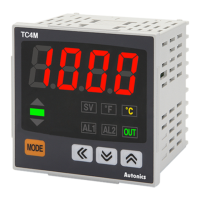
M
DIN W72
H72mm
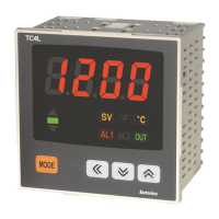
H
DIN W48
H96mm
W
DIN W96
H48mm
L
DIN W96
H96mm
4
9999 (4 Digit)
C
Set by touch switch
T
Temperature controller
1
3
2
6
4
1
2
3 5 4
6 7, 8
5
8
7
※
TC4 Series has selectable control output; Relay output, and SSR drive output.
AC/DC power type does not have SSRP function.
Series
TC4 Series
TC4S TC4SP TC4Y TC4M TC4W TC4H TC4L
Power
supply
AC power 100-240VAC
ᜠ
50/60Hz
AC/DC Power 24VAC
ᜠ
50/60Hz, 24-48VDC
ᜡ
Allowable voltage range 90 to 110% of rated voltage
Power
consumption
AC power Max. 5VA (100-240VAC 50/60Hz)
AC/DC Power
Max. 5VA (24VAC 50/60Hz), Max. 3W (24-48VDC)
Display method 7Segment (Red), Other display (Green, Yellow, Red LED)
Character size (W×H) 7.0×15.0mm
7.4×15.0mm 9.5×20.0mm 9.5×20.0mm 7.0×14.6mm
11.0×22.0mm
Input
type
RTD DPt100Ω, Cu50Ω (Allowable line resistance max.5Ω per a wire)
TC K (CA), J (IC), L (IC)
Display
accuracy
※
1
RTD
At room temperature (23
℃
±5
℃
): (PV ±0.5% or ±1
℃
, select the higher one) ±1digit
Out of room temperature range: (PV ±0.5% or ±2
℃
, select the higher one) ±1digit
※
For TC4SP, add ±1
℃ by accuracy standard.
TC
Control
output
Relay 250VAC
ᜠ
3A 1a
SSR 12VDC
ᜡ
± 2V 20mA Max.
Alarm output AL1, AL2 Relay: 250VAC
ᜠ
1A 1a (
※
TC4SP, TC4Y have AL1 only.)
Control method ON/OFF and P, PI, PD, PID control
Hysteresis 1 to100
℃
/
℉
(0.1 to 50.0
℃
/
℉
) variable
Proportional band (P) 0.1 to 999.9
℃
/
℉
Integral time (I) 0 to 9999 sec.
Derivative time (D) 0 to 9999 sec.
Control period (T) 0.5 to 120.0 sec.
Manual reset 0.0 to 100.0%
Sampling period 100ms
Dielectric
strength
AC power 2,000VAC 50/60Hz for 1min. (between input terminal and power terminal)
AC/DC Power 1,000VAC 50/60Hz for 1min. (between input terminal and power terminal)
Vibration 0.75mm amplitude at frequency of 5 to 55Hz in each X, Y, Z direction for 2 hours
Relay
life cycle
Mechanical OUT: Min. 5,000,000 operations, AL1/2: Min. 5,000,000 operations
Electrical
OUT: Min. 200,000 operations (250VAC 3A resistive load),
AL1/2: Min. 300,000 operations (250VAC 1A resistive load)
Insulation resistance Min. 100MΩ (at 500VDC megger)
Noise immunity
Square-wave noise by noise simulator (pulse width 1
㎲
) ± 2KV R-phase and S-phase
Memory retention Approx. 10 years (When using non-volatile semiconductor memory type)
Environ
-ment
Ambient temp.
-10 to 50
℃
, Storage: -20 to 60
℃
Ambient humi.
35 to 85%RH, Storage: 35 to 85%RH
Insulation type
Double insulation or reinforced insulation (mark: , Dielectric strength between the
measuring input part and the power part: AC power 2kV, AC/DC Power 1kV)
Approval
Weight
※
2
Approx. 141g
(approx. 94g)
Approx. 123g
(approx. 76g)
Approx. 174g
(approx. 85g)
Approx. 204g
(approx. 133g)
Approx. 194g
(approx. 122g)
Approx. 194g
(approx. 122g)
Approx. 254g
(approx. 155g)
1. Present temperature (PV) display
RUN mode: Present temperature (PV) display.
Parameter setting mode: Parameter or
parameter setting valuedisplay.
2. Deviation indicator, Auto-tuning indicator
It shows current temperature (PV) deviation
based on set temperature (SV) by LED.
The deviation indicators ( , , ) flash by
every 1 sec. when operating auto tuning.
3. Set temperature (SV) indicator
Press any front key once to check or change
current set temperature (SV), the set
temperature (SV) indicator is ON and preset set
value is flashed.
4. Temperature unit
(℃/℉)
indicator
It shows current temperature unit.
5. Control/alarm output indicator
OUT: It will turn ON when control output (Main Control
Output) is ON.
※
In case of CYCLE/PHASE control of SSR drive
output, it will turn ON when MV is over 3.0%.
(only for AC power type)
AL1/AL2: It will light up when alarm output Alarm1/
Alarm2 are on.
6. key
Used when entering into parameter group, returning
to RUN mode, moving parameter, and saving setting
values.
7. Adjustment
Used when entering into set value change mode, digit
moving and digit up/down.
8. FUNCTION key
Press + keys for 3 sec. to operate function (RUN/
STOP, alarm output cancel, auto-tunning) set in inner
parameter [
DI-K
].
※
Press + keys at the same time in set value
operation to move digit.
No.
PV deviation temp. Deviation display
1
Over 2
℃
indicator ON
2
Below ±2
℃
indicator ON
3
Under -2
℃
indicator ON
Input sensor Display Temperature range (
℃
) Temperature range (
℉
)
Thermocouple
K (CA)
KCA
-50 to 1200 -58 to 2192
J (IC)
JIC
-30 to 500 -22 to 932
L (IC)
LIC
-40 to 800 -40 to 1472
RTD
DPt100Ω
DPtH
-100 to 400 -148 to 752
DPtL
-100.0 to 400.0 -148.0 to 752.0
Cu50Ω
CUsH
-50 to 200 -58 to 392
CUsL
-50.0 to 200.0 -58.0 to 392.0
※
Mount the product on the panel, fasten bracket by pushing with tools as shown above.
(In case of TC4Y, fasten bolts for bracket.)
TC4S Series
RSA-COVER (48×48mm) RMA-COVER (72×72mm)
RHA-COVER
(48×96mm, 96×48mm )
RLA-COVER (96×96mm )
TC4SP Series
TC4Y Series
TC4M Series
Bracket
TC4L Series TC4H Series
TC4W Series
Terminal cover (sold separately)
Panel cut-out
Size
Model
A B C D
TC4S Min. 65 Min. 65 45
+0.6
0
45
+0.6
0
TC4SP Min. 65 Min. 65 45
+0.6
0
45
+0.6
0
TC4Y Min. 91 Min. 40 68
+0.7
0
31.5
+0.5
0
TC4M Min. 90 Min. 90 68
+0.7
0
68
+0.7
0
TC4H Min. 65 Min. 115 45
+0.6
0
92
+0.8
0
TC4W Min. 115 Min. 65 92
+0.8
0
45
+0.6
0
TC4L Min. 115 Min. 115 92
+0.8
0
92
+0.8
0
TC4S/TC4SP Series TC4Y Series
TC4M, TC4W, TC4H, TC4L Series
48
45
64.56 48 58.5 45
72.2
6
64.5
67.5
72 6
30
60
104.4
3.5 10
12
46
23.9
12
37.5
40.5
3.34
A
C
D
B
48
44.7
64.596 6
91.5
64.5696
96
91.5
48
64.56
70
68.5
3
64
13
91.5
86
4
13
47.2
91.5
86
3
13
94
72 77
84
7
36
30
TC4S Series
TC4Y Series
TC4M Series
TC4SP Series
TC4H, TC4W, TC4L Series
※
1: AC power: 100-240VAC 5VA 50/60Hz
AC/DC power: 24VAC 5VA 50/60Hz
24-48VDC 3W
AL1 OUT:
250VAC 1A 1a
SSR OUT:
12VDC ±2V
20mA Max
SOURCE
100-240VAC 5VA 50/60Hz
24VAC 5VA 50/60Hz
24-48VDC 3W
-
+
B'
※
1
B
A
RTD
SENSOR
TC
-
+
AL2 OUT:
250VAC 1A 1a
Relay OUT:
250VAC 3A 1a
1 7
2 8
3 9
4 10
5 11
6 12
AL1 OUT:
250VAC 1A 1a
SSR OUT:
12VDC ±2V
20mA Max
SOURCE
100-240VAC 5VA 50/60Hz
24VAC 5VA 50/60Hz
24-48VDC 3W
※
1
-
+
-
+
AL2 OUT:
250VAC 1A 1a
Relay OUT:
250VAC 3A 1a
B'
B
A
RTD
SENSOR
TC
1
10
13
22
2
11
14
23
3
12
15
24
4 16
5 17
6 18
7 19
8 20
9 21
AL1 OUT:
250VAC 1A 1a
SSR OUT:
12VDC ±2V
20mA Max
SOURCE
100-240VAC 5VA 50/60Hz
24VAC 5VA 50/60Hz
24-48VDC 3W
B'
※
1
BA
- +
SENSOR
TC
RTD
Relay OUT:
250VAC 3A 1a
1 2 3 4 5 6 7 8 9 10 11
●
SSRP function is selectable one of standard ON/OFF control, cycle control, phase control by utilizing
standard SSR drive output.
● Realizing high accuracy and cost effective temperature control as linear output(cycle control and
phase control).
● Select one of standard ON/OFF control [
STND
], cycle control [
CYCL
] , phase control [
PHAS
] at [
SSrM
]
parameter of Parameter group 2. For cycle control, connect zero cross turn-on SSR or random
turn-on SSR. For phase control, connect random turn-on SSR.
SSR Drive Output Selection Function (SSRP Function)[
SSrM
]
※
When selecting cycle or phase control mode,
the power supply for a load and a temperature
controller must be the same.
※
In case of selecting cycle [
CYCL
] or phase [
PHAS
] control mode for PID control, control cycle [
T
] is
not allowed to set.
※
For AC/DC power model (TC4 - 2R), this parameter [
SSrM
] is not displayed and it is available only
standard control by relay or SSR.
1)Standard ON/OFF control [
STND
]
A mode to control the load in the
same way as Relay output type.
(ON: output level 100%,
OFF: output level 0%)
2)Cycle control [
CYCL
]
A mode to control the load by
repeating output ON / OFF
according to the rate of output
within setting cycle.
Having improved ON / OFF noise
feature by Zero Cross type.
3)Phase control
[
PHAS
]
A mode to control the load by
controlling the phase within
AC half cycle. Serial control is
available.
Random turn-on SSR must be
used for this mode.
50Cycle 50Cycle
50% 80%
AC
OUT
ON ONOFF OFF
AC
OUT
10% 50%
AC
OUT
SSR voltage output
(12VDC)
Load
Power
100-240VAC
50/60Hz
Temperature controller
(TC4Series)
SSR module
※
The above specications are subject to change and some models may be discontinued
without notice.
※
Be sure to follow cautions written in the instruction manual and the technical descriptions
(catalog, homepage).
Thank you for choosing our Autonics product.
Please read the following safety considerations before use.
Safety Considerations
※
Please observe all safety considerations for safe and proper product operation to avoid hazards.
※
Safety considerations are categorized as follows.
Warning
Failure to follow these instructions may result in serious injury or death.
Caution
Failure to follow these instructions may result in personal injury or product damage.
※
The symbols used on the product and instruction manual represent the following
symbol represents caution due to special circumstances in which hazards may occur.
31
55
56
20
15
21
5
45
16
48.6
44.9
36
48.4
9.8
41.5
18
22
22.5
1. Fail-safe device must be installed when using the unit with machinery that may cause serious injury
or substantial economic loss. (e.g. nuclear power control, medical equipment, ships, vehicles,
railways, aircraft, combustion apparatus, safety equipment, crime/disaster prevention devices, etc.)
Failure to follow this instruction may result in re, personal injury, or economic loss.
2. Install on a device panel to use.
Failure to follow this instruction may result in electric shock or re.
3. Do not connect, repair, or inspect the unit while connected to a power source.
Failure to follow this instruction may result in electric shock or re.
4. Check 'Connections' before wiring.
Failure to follow this instruction may result in re.
5. Do not disassemble or modify the unit.
Failure to follow this instruction may result in electric shock or re.
1. When connecting the power input and relay output, use AWG 20(0.50mm
2
) cable or over and tighten
the terminal screw with a tightening torque of 0.74~0.90N
.
m.
When connecting the sensor input and communication cable without dedicated cable, use AWG
28~16 cable and tighten the terminal screw with a tightening torque of 0.74~0.90N
.
m.
Failure to follow this instruction may result in re or malfunction due to contact failure.
2. Use the unit within the rated specications.
Failure to follow this instruction may result in re or product damage.
3. Use dry cloth to clean the unit, and do not use water or organic solvent.
Failure to follow this instruction may result in electric shock or re.
4. Do not use the unit in the place where ammable/explosive/corrosive gas, humidity, direct sunlight,
radiant heat, vibration, impact, or salinity may be present.
Failure to follow this instruction may result in re or explosion.
5. Keep metal chip, dust, and wire residue from owing into the unit.
Failure to follow this instruction may result in re or product damage.
SSR OUT:
12VDC ±2V
20mA Max
SOURCE
100-240VAC 5VA 50/60Hz
24VAC 5VA 50/60Hz
24-48VDC 3W
B'
※
1
B
A
RTD
SENSOR
TC
-
+
-
+
-
+
Relay OUT
250VAC 3A 1a
1
2
3
4
5
6
7
8
9
10
11
AL1 OUT:
250VAC 1A 1a
SSR OUT:
12VDC ±2V
20mA Max
SOURCE
100-240VAC 5VA 50/60Hz
24VAC 5VA 50/60Hz
24-48VDC 3W
-
+
B'
B
A
RTD
SENSOR
TC
AL1 OUT:
250VAC 1A 1a
AL2 OUT:
250VAC 1A 1a
Relay OUT:
250VAC 3A 1a
1 10
2 11
3 12
4 13
5 14
6 15
7 16
8 17
9 18
DRW170775AA
(unit: mm)
<Crimp terminal>
a
b
c
Terminal number
a b c
1 to N 6 Max. 1.9 Max. 4.0
(unit: mm)
※
Use crimp terminals or teminals of size specied below.
a
b
<Round>
a
b
<Forked>
a Min. 3.0mm Min. 3.0mm
b Max.5.8mm Max.5.8mm
Warning
Caution