H-63
Economical PID Control
(A)
Photoelectric
Sensors
(B)
Fiber
Optic
Sensors
(C)
Door/Area
Sensors
(D)
Proximity
Sensors
(E)
Pressure
Sensors
(F)
Rotary
Encoders
(G)
Connectors/
Sockets
(H)
Temperature
Controllers
(I)
SSRs / Power
Controllers
(J)
Counters
(K)
Timers
(L)
Panel
Meters
(M)
Tacho /
Speed / Pulse
Meters
(N)
Display
Units
(O)
Sensor
Controllers
(P)
Switching
Mode Power
Supplies
(Q)
Stepper Motors
& Drivers
& Controllers
(R)
Graphic/
Logic
Panels
(S)
Field
Network
Devices
(T)
Software
Functions
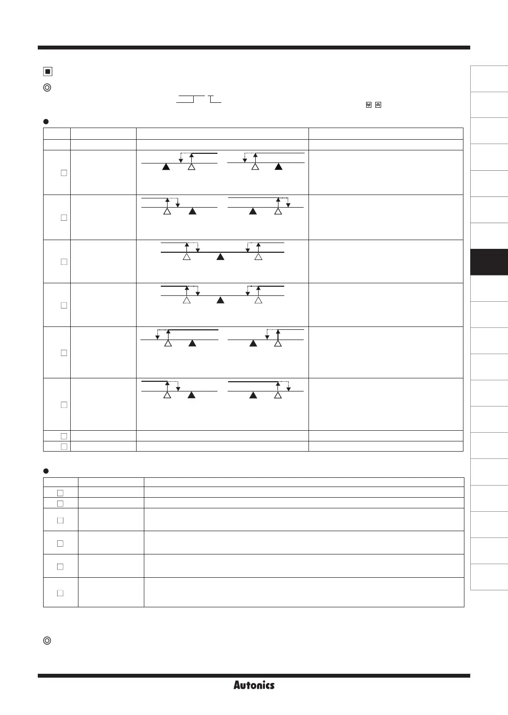
Alarm operation
Alarm [
AL-1
/
AL-2
]
Alarm
operation
Alarm
option
AM!A
Sensor break alarm
The function that alarm output will be ON when sensor is not connected or when sensor's disconnection is detected during temperature
controlling. You can check whether the sensor is connected with buzzer or other units using alarm output contact. It is selectable between
standard alarm [
SBaA
], or alarm latch [
SBaB
].
Alarm option
Mode Name Description
AM .A
Standard alarm If it is an alarm condition, alarm output is ON. If it is a clear alarm condition, alarm output is OFF.
AM .B
Alarm latch If it is an alarm condition, alarm output is ON and maintains ON status. (Alarm output HOLD)
AM .C
Standby sequence 1
First alarm condition is ignored and from second alarm condition, standard alarm operates.
When power is supplied and it is an alarm condition, this rst alarm condition is ignored and from the
second alarm condition, standard alarm operates.
AM .D
Alarm latch and
standby sequence 1
If it is an alarm condition, it operates both alarm latch and standby sequence. When power is supplied
and it is an alarm condition, this rst alarm condition is ignored and from the second alarm condition,
alarm latch operates.
AM .E
Standby sequence 2
First alarm condition is ignored and from second alarm condition, standard alarm operates.
When re-applied standby sequence and if it is alarm condition, alarm output does not turn ON.
After clearing alarm condition, standard alarm operates.
AM .F
Alarm latch and
standby sequence 2
Basic operation is same as alarm latch and standby sequence 1. It operates not only by power ON/OFF,
but also alarm setting value, or alarm option changing. When re-applied standby sequence and if it is
alarm condition, alarm output does not turn ON.
After clearing alarm condition, alarm latch operates.
Mode Name Alarm operation Description
AM)_
- -
No alarm output
AM!
Deviation
high-limit
alarm
SV
100℃
PV
110℃
OFF ONH
PV
90℃
SV
100℃
OFF ONH
If deviation between PV and SV as high-limit is
higher than set value of deviation temperature,
the alarm output will be ON.
High deviation: Set as 10℃ High deviation: Set as -10℃
AM@
Deviation
low-limit
alarm
PV
90℃
SV
100℃
OFFON H
SV
100℃
PV
110℃
OFFON H
If deviation between PV and SV as low-limit is
higher than set value of deviation temperature,
the alarm output will be ON.
Lower deviation: Set as 10℃ Lower deviation: Set as -10℃
AM#
Deviation
high/low-limit
alarm
PV
90℃
PV
110℃
SV
100℃
OFFON ONH H
If deviation between PV and SV as high/low-limit
is higher than set value of deviation temperature,
the alarm output will be ON.
High/Lower deviation: Set as 10℃
AM$
Deviation
high/low-limit
reserve alarm
PV
90℃
PV
110℃
SV
100℃
OFFON ONH H
If deviation between PV and SV as high/low-limit
is higher than set value of deviation temperature,
the alarm output will be OFF.
High/Lower deviation: Set as 10℃
AM%
Absolute
value high
limit alarm
PV
90℃
SV
100℃
OFF ONH
SV
100℃
PV
110℃
OFF ONH
If PV is higher than the absolute value,
the output will be ON.
Absolute-value Alarm:
Set as 90℃
Absolute-value Alarm:
Set as 110℃
AM^
Absolute
value low
limit alarm
PV
90℃
SV
100℃
OFFON H
SV
100℃
PV
110℃
OFFON H
If PV is lower than the absolute value,
the output will be ON.
Absolute-value Alarm:
Set as 90℃
Absolute-value Alarm:
Set as 110℃
SBa
Sensor break Alarm
-
It will be ON when it detects sensor disconnection.
LBa
Loop break Alarm
-
It will be ON when it detects loop break.
※
H: Alarm output hysteresis [
AHYS
]
※
Condition of re-applied standby sequence for standby sequence 1, alarm latch and standby sequence 1: Power ON
Condition of re-applied standby sequence for standby sequence 2, alarm latch and standby sequence 2: Power ON, changing set
temperature, alarm temperature [
AL1
,
AL2
] or alarm operation [
AL-1
,
AL-2
], switching STOP mode to RUN mode.
Set both alarm operation and alarm option by combining.
Each alarm operates individually in two alarm output models.
When the current temperature is out of alarm range, alarm clears
automatically. If alarm option is alarm latch or alarm latch and standby
sequence 1/2, press digital input key(
+ 3 sec., digital input
key[
DI-K
] of Parameter group 2 set as
AlRE
), or turn OFF the power
and turn ON to clear alarm.
 Loading...