I N S T R U C T I O N M A N U A L
High Accuracy PID Temperature Controller
TK4 SERIES
※
1. In case of TK4N/SP Series, option control selection and digital input will be limited due to number of terminals.
※
2. "S" represents SSR drive output support models which SSRP function (standard ON/OFF, cycle, phase)
control are available. "C" represents selectable current and SSR drive output support models.
※
3. Select "R" or "C" type in case of using heating&cooling control and "N" type in case of using standard control.
※
4. Does not support in AC/DC voltage type model.
※
5. Does not support in TK4N.
※
6. The CT input model of TK4N is selectable only for standard model which has alarm output 1.
※
7. The heating&cooling model of TK4N-1 has only alarm output 2.
※
8. Only for TK4S-D , OUT2 output terminal is used as DI-2 input terminal.
※
9. 11Pin socket (PG-11, PS-11(N)) for TK4SP: sold separately.
※
1:
At room temperature range (23
℃
±5
℃
)
Thermocouple K, J, T, N, E type, below -100
℃
/ Thermocouple L, U, PL
Ⅱ
, Cu50Ω, DPt 50Ω:
(PV ±0.3% or ±2
℃
, select the higher one) ±1-digit
Thermocouple C, G, R, S type, below 200
℃
: (PV ±0.3% or ±3
℃
, select the higher one)±1-digit
Thermocouple B type, below 400
℃
: there is no accuracy standards.
Out of room temperature range
RTD Cu50Ω, DPt50Ω: (PV ±0.5% or ±3
℃
, select the higher one) ±1-digit
Thermocouple R, S, B, C, G type: (PV ±0.5% or ±5
℃
, select the higher one) ±1-digit
Others, below -100
℃
: within ±5
℃
In case of TK4SP Series, ±1
℃
will be added to the degree standard.
※
2: The weight includes packaging. The weight in parenthesis is for unit only.
※
Environment resistance is rated at no freezing or condensation.
1. Measured value (PV) display part
: RUN mode: It displays currently measured value (PV).
Setting mode: It displays the parameter.
2. Set value (SV) display part:
RUN mode: It displays the set value (SV).
Setting mode: It displays the set value of the parameter.
3. Unit (
℃
/
℉
/%) indicator
: It displays the unit set at display unit [
UNIT
] in parameter 3 group.
(In case of TK4N, % is not supported)
4. Manual control indicator
: It turns ON during manual controlling.
5. Multi SV indicator
: One of SV1 to 3 lamps will be ON in case of selecting multi SV function.
6. Auto tuning indicator
: It ashes by 1 sec. when executing auto tuning.
7. Alarm output (AL1, AL2) indicator
: It turns ON when the alarm output is ON.
8. Control output (OUT1, OUT2) indicator
: It turns ON when the control output is ON.
※
During cycle/phase controlling in SSRP function model (TK4 - 4S ), when MV is over 5.0%, it turns ON.
※
To use current ouput, when MV is 0.0% in manual control, it turns OFF. Otherwise, it always turns ON.
When MV is over 3.0% in auto control, it turns ON and when MV is below 2.0%, it turns OFF.
9. key
: It is used when switching auto control to manual control.
※
TK4N/S/SP do not have the
key. The
key operates switching simultaneously.
10. key
: It is used when entering parameter groups, returning to RUN mode, moving parameter,
saving the set value.
11. , , keys
: It is used when entering the set value changing mode and moving or changing up/down digit.
12. Digital input key
: When pressing + keys for 3 sec. at the same time, it operates the function
(RUN/STOP, alarm clear, auto tuning) set at digital input key [
DI-K
] in parameter 5 group.
13. PC loader port
: It is the PC loader port for serial communication to set parameter and monitor with
DAQMaster installed in PC. Use this for connecting SCM-US (USB/Serial converter, sold separately).
※
Standard model has shaded terminals only.
※
When the
operation mode of heating&cooling OUT2 relay output model is heating or cooling control, the
OUT2 is usable as alarm output 3 (except TK4N Series).
※
When the
operation mode of heating&cooling OUT2 current output model is heating or cooling control, the
OUT2 is usable as transmission output 2.
●TK4N (48 × 24mm) Series
●TK4H, TK4W, TK4L
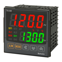
●TK4M
●TK4SP
●TK4S
※
The input selection switch (TC, RTD/mV, V, mA) disappeared.
Select input type [
IN-T
] in parameter 3 group.
●TK4S/SP (48 × 48mm) Series ●Other Series
※
Shaded descriptions are upgraded or added functions from the before TK Series.
※
The above specications are subject to change and some models may be discontinued without notice.
※
Be sure to follow cautions written in the instruction manual, user manual and the technical descriptions
(catalog, homepage).
Ordering Information
Series
TK4N TK4SP TK4S TK4M TK4W TK4H TK4L
Power
supply
AC voltage 100-240VAC 50/60Hz
AC/DC voltage
-
24VAC 50/60Hz, 24-48VDC
Allowable voltage range 90 to 110% of rated voltage
Power
consumption
AC voltage Max. 6VA Max. 8VA
AC/DC voltage
-
Max. 8VA (24VAC 50/60Hz), max. 5W (24-48VDC)
Display method 7-segment (PV: red, SV: green), other display part (green, yellow, red) LED method
Character
size
PV (W×H) 4.5×7.2mm 7.0×14.0mm 9.5×20.0mm 8.5×17.0mm 7.0×14.6mm 11.0×22.0mm
SV (W×H) 3.5×5.8mm 5.0×10.0mm 7.5×15.0mm 6.0×12.0mm 6.0×12.0mm 7.0×14.0mm
Input
type
RTD JPt 100Ω, DPt 100Ω, DPt 50Ω, Cu 100Ω, Cu 50Ω, Nikel 120Ω (6 types)
Thermcouple K, J, E, T, L, N, U, R, S, B, C, G, PLII (13 types)
Analog
·Voltage: 0-100mVDC , 0-5VDC , 1-5VDC , 0-10VDC (4 types)
·Current: 0-20mA, 4-20mA (2 types)
Display
accuracy
RTD ·At room temperature (23
℃
±5
℃
): (PV
±0.3% or
±1
℃
, select the higher one)
±1-digit
※
1
·Out of room temperature ranges: (PV
±0.5% or
±2
℃
, select the higher one)
±1-digit
In case of TK4SP Series,
±1
℃
will be added.
Thermcouple
Analog
·At room temperature (23
℃
±5
℃
):
±0.3% F.S.
±1-digit
·Out of room temperature ranges:
±0.5% F.S.
±1-digit
CT input ±5% F.S. ±1-digit
Control
output
Relay OUT1, OUT2: 250VAC 3A 1a
SSR Max. 11VDC
±2V 20mA
Current DC4-20mA or DC0-20mA selectable (resistance load: max. 500Ω)
Alarm output
Relay AL1, AL2: 250VAC 3A 1a
※
TK4N AL2: 250VAC 0.5A, 1a (max. 125VA), TK4SP has only AL1
Option
output
Transmission DC4-20mA (resistance load: max. 500Ω, output accuracy:
±0.3% F.S.)
Communication RS485 communication output (Modbus RTU)
Option
input
CT 0.0-50.0A (primary heater current reading range)
※
CT ratio is 1/1000 (except TK4SP)
Digital input
·Contact input: ON - max. 2kΩ, OFF - min. 90kΩ
·Non-contact input: ON - residual votage max. 1.0VDC , OFF - leakage current max. 0.1mA
·Outflow current: approx. 0.5mA per input
※
TK4S/M: 1 (TK4S-D : 2, TK4SP: none), TK4N/H/W/L: 2 (except TK4SP)
Control
method
Heating, Cooling
ON/OFF, P, PI, PD, PID control mode
Heating&Cooling
Hysteresis ·RTD/Thermcouples: 1 to 100
℃
/
℉
(0.1 to 100.0
℃
/
℉
) variable ·Analog: 1 to 100-digit
Proportional band (P) 0.1 to 999.9
℃
/
℉
(0.1 to 999.9%)
Integral time (I) 0 to 9999 sec
Derivative time (D) 0 to 9999 sec
Control period (T)
·
R
elay output, SSR drive output: 0.1 to 120.0 sec
·Current output+SSR drive output: 1.0 to 120.0 sec
Manual reset value 0.0 to 100.0%
Sampling period 50ms
Dielectric strength 2,000VAC 50/60Hz for 1 min (between power source terminal and input terminal)
Vibration 0.75mm amplitude at frequency of 5 to 55Hz (for 1 min) in each X, Y, Z direction for 2 hours
Relay
life cycle
Mechanical
·OUT1/OUT2: min. 5,000,000 operations,
·AL1/AL2: min. 20,000,000 operations (TK4H/W/L: min. 5,000,000 operations)
Electrical OUT1/OUT2, AL1/AL2: min. 100,000 operations
Insulation resistance Over 100MΩ (at 500VDC megger)
Noise immunity Square shaped noise by noise simulator (pulse width 1
㎲
)
±2kV R-phase, S-phase
Memory retention Approx. 10 years (non-volatile semiconductor memory type)
Environ
-ment
Ambient temp. -10 to 50
℃
, storage: -20 to 60
℃
Ambient humi. 35 to 85%RH, storage: 35 to 85%RH
Protection IP65 (front panel)
※
TK4SP: IP50 (front panel)
Insulation type
Double insulation or reinforced insulation
(mark: , dielectric strength between the measuring input part and the power part : 2kV)
Approval
Weight
※
2
Approx. 140g
(approx. 70g)
Approx. 130g
(approx. 85g)
Approx. 150g
(approx. 105g)
Approx. 210g
(approx. 140g)
Approx. 211g
(approx. 141g)
Approx. 294g
(approx. 198g)
Specications Connections
Dimensions
Installation
Unit Description
※
Insert the unit into a panel,
fasten the bolt with a (+) driver.
※
Insert the unit into a panel,
fasten the bracket by pushing with tools with a (-) driver.
(+) driver
(-) driver
(-) driver
13
5
4
7
8
6
1
3
2
12
9 10 11
RS485(B-)
RS485(A+)
Transfer Output
DC4-20mA
Current Transformer
0.0-50.0A
Digital Input
Non-contact, contact input
AL2 OUT:
250VAC 0.5A 1a
RESISTIVE LOAD
OUT2/AL1 OUT:
250VAC 3A 1a
RESISTIVE LOAD
OUT1:
250VAC 3A 1a
RESISTIVE LOAD
SSR
11VDC±2V
20mA Max.
SSR
11VDC±2V
20mA Max.
Current
DC0/4-20mA
Load 500Ω Max.
Current
DC0/4-20mA
Load 500Ω Max.
SOURCE
100-240VAC
50/60Hz 6VA
SENSOR
TC
RTD
+
+
+
+
+ +
+ +
-
-
-
-
- -
- -
B' B A
Communication Output
●TK4N
mA
mA
mA
mA
CT
DI-2
DI-2
DI-1
DI-1
7
1
8
2
9
3
10
4
11
5
12
6
Current
DC0/4-20mA
Load 500
Ω
Max.
SSR
11VDC
±
2V
20mA Max.
Current
Transformer
0.0-50.0A
Digital Input
Non-contact,
Contact Input
Transfer
Output
DC4-20mA
AL1 OUT:
250VAC 3A 1a
RESISTIVE LOAD
AL2 OUT:
250VAC 3A 1a
RESISTIVE LOAD
OUT2:
Relay
250VAC 3A 1a
RESISTIVE LOAD
OUT1:
Relay
250VAC 3A 1a
RESISTIVE LOAD
mA
mA
mA
CT
mA
DI-1 DI-1
1 1019
2 1120
3 1221
4 1322
5 1423
6 1524
7 1625
8 1726
9 1827
RS485(B-)
Communication Output
RS485(A+)
SENSOR
TC
RTD
+ +
+
+ +
+
++
- -
-
- - -
--
B'
B
A
SENSOR
OUT2:
Relay
250VAC 3A 1a
RESISTIVE LOAD
AL1 :
Relay
250VAC 3A 1a
RESISTIVE LOAD
OUT1:
Relay
250VAC 3A 1a
RESISTIVE LOAD
Current
DC0/4-20mA
Load 500
Ω
Max.
SSR
11VDC
±
2V
20mA Max.
SSR
11VDC
±
2V
20mA Max.
Current
DC0/4-20mA
Load 500
Ω
Max.
mA
mA
mA
6
5
4
3
2
1
11
10
9
8
7
TC
RTD
+ +
-
- -
--
- -
+
+ +
+
+
B'
B
A
●Panel cut-out
A
D
B
C
Size
Model
A B C D
TK4N 55 37 45
+ 0.6
0
22.2
+ 0.3
0
TK4S 65 65 45
+ 0.6
0
45
+ 0.6
0
TK4S (P) 65 65 45
+ 0.6
0
45
+ 0.6
0
TK4M 90 90 68
+ 0.7
0
68
+ 0.7
0
TK4H 65 115 45
+ 0.6
0
92
+ 0.8
0
TK4W 115 65 92
+ 0.8
0
45
+ 0.6
0
TK4L 115 115 92
+ 0.8
0
92
+ 0.8
0
(unit: mm)
(unit: mm)
Digital Input
Non-contact,
Contact Input
Digital Input
Non-contact,
Contact Input
Current
DC0/4-20mA
Load 500
Ω
Max.
AL1 OUT:
250VAC 3A 1a
RESISTIVE LOAD
SSR
11VDC
±
2V
20mA Max.
OUT1:
Relay
250VAC 3A 1a
RESISTIVE LOAD
OUT2:
Relay
250VAC 3A 1a
RESISTIVE LOAD
Current
Transformer
0.0-50.0A
Transfer
Output
DC4-20mA
AL2 OUT:
250VAC 3A 1a
RESISTIVE LOAD
Current
DC0/4-20mA
Load 500Ω Max.
SSR
11VDC±2V
20mA Max.
mA
mA
mA
CT
DI-1 DI-2DI-1 DI-2
1
7
2
8
3
9
4
10
5
11
6
12
18
17
16
15
14
13
RS485(B-)
Communication Output
RS485(A+)
SENSOR
TC
RTD
+
+
+
+ +
+
+
+
-
-
-
- -
-
- -
B'
B
A
mA
Current
DC0/4-20mA
Load 500
Ω
Max.
SSR
11VDC
±
2V
20mA Max.
Current
Transformer
0.0-50.0A
Transfer Output
DC4-20mA
Digital Input
Non-contact,
Contact Input
AL1 OUT:
250VAC 3A 1a
RESISTIVE LOAD
AL2 OUT:
250VAC 3A 1a
RESISTIVE LOAD
OUT2:
Relay
250VAC 3A 1a
RESISTIVE LOAD
OUT1:
Relay
250VAC 3A 1a
RESISTIVE LOAD
mA
mA
mA
mA
CT
DI-1
DI-2
1
13
2
14
3
15
4
16
5
17
6
18
7
19
8
20
9
21
10
22
11
23
12
24
RS485(B-)
Communication Output
RS485(A+)
SENSOR
TC
RTD
+
+
+ +
+
+
+
+
-
-
- -
-
-
- -
B'
B
A
DI-1
DI-2
●TK4N Series
3
94.8
21.8
48
24
●TK4H Series
1.5
6
64.5
91.5
96
48
●TK4W Series
48
96
44.7
1.5
6
64.5
Terminal cover (sold separately)
RSA-COVER (48×48mm) TK4N COVER (48×24mm)
※
TK4N COVER is accessory.
RMA-COVER (72×72mm)
70
68.5
3
64
13
RLA-COVER (96×96mm)
RHA-COVER
(48×96mm, 96×48mm)
91.5
86
4
13
47.2
91.5
86
3
13
94
TK4N Series
TK4S, TK4SP Series TK4M/W/H/L Series
46
23.9
12
37.5
40.5
3.34
●Bracket
28.8
22
36.3
42
45.2
48.6
26.4
32.4
10
3.5
11.6
7.9
●TK4SP Series
6
72.2
44.8
48
●TK4M Series
1.7
6
64.5
67.5
72
●TK4S Series
1.7
6
64.5
45
48
●TK4L Series
96
91.5
1.5
6
64.5
21.8
6.2
44.6
48.4
9.8
41.5
18
22
22.5
Thank you for choosing our Autonics product.
Please read the following safety considerations before use.
Safety Considerations
Warning
Caution
※
Please observe all safety considerations for safe and proper product operation to avoid hazards.
※
Safety considerations are categorized as follows.
Warning
Failure to follow these instructions may result in serious injury or death.
Caution
Failure to follow these instructions may result in personal injury or product damage.
※
The symbols used on the product and instruction manual represent the following
symbol represents caution due to special circumstances in which hazards may occur.
1. Fail-safe device must be installed when using the unit with machinery that may cause serious injury
or substantial economic loss. (e.g. nuclear power control, medical equipment, ships, vehicles,
railways, aircraft, combustion apparatus, safety equipment, crime/disaster prevention devices, etc.)
Failure to follow this instruction may result in re, personal injury, or economic loss.
2. Install on a device panel to use.
Failure to follow this instruction may result in electric shock.
3. Do not connect, repair, or inspect the unit while connected to a power source.
Failure to follow this instruction may result in electric shock or re.
4. Check 'Connections' before wiring.
Failure to follow this instruction may result in re.
5. Do not disassemble or modify the unit.
Failure to follow this instruction may result in electric shock or re.
1. When connecting the power input and relay output, use AWG 20 (0.50mm
2
) cable or over and tighten
the terminal screw with a tightening torque of 0.74~0.90N m.
When connecting the sensor input and communication cable without dedicated cable, use AWG 28~16
cable or over and tighten the terminal screw with a tightening torque of 0.74~0.90N m.
Failure to follow this instruction may result in re or malfunction due to contact failure.
2. Use the unit within the rated specications.
Failure to follow this instruction may result in re or product damage.
3. Use dry cloth to clean the unit, and do not use water or organic solvent.
Failure to follow this instruction may result in electric shock or re.
4. Do not use the unit in the place where ammable/explosive/corrosive gas, humidity, direct sunlight,
radiant heat, vibration, impact, or salinity may be present.
Failure to follow this instruction may result in re or explosion.
5. Keep metal chip, dust, and wire residue from owing into the unit.
Failure to follow this instruction may result in re or product damage.
SOURCE
100-240VAC 50/60Hz 8VA
24VAC 50/60Hz 8VA
24-48VDC 5W
-
+
SOURCE
100-240VAC 50/60Hz 8VA
24VAC 50/60Hz 8VA
24-48VDC 5W
-
+
SOURCE
100-240VAC 50/60Hz 8VA
24VAC 50/60Hz 8VA
24-48VDC 5W
-
+
SOURCE
100-240VAC 50/60Hz 8VA
24VAC 50/60Hz 8VA
24-48VDC 5W
-
+
31
55
56
20
15
21
5
45
16
48.6
44.9
36
DRW170598A A
OUT2 control
output
※
3
OUT1 control
output
※
2
Power supply
Size
Digit
Item
Input/Output option
※
1
TK 4 N 1 4 R N
Standard
N
None
※
Select in case of standard control (heating or cooling)
Heating&
Cooling
R
Relay output
C
Current output or SSR drive output selectable
R
Relay output
S
※
4
SSR drive output (standard ON/OFF, cycle control, phase control)
C
Current output or SSR drive output selectable
4
9999 (4-digit)
TK
Temperature / Process Controller
N
1
Standard Alarm output 1+CT input
※
6
Heating&Cooling
Alarm output 2
※
7
2
Standard Alarm output 1+Alarm output 2
D
Standard Alarm output 1+Digital input (DI-1, DI-2)
Heating&Cooling
Digital input (DI-1, DI-2)
R
Standard Alarm output 1+Transmission output
Heating&Cooling
Transmission output
T
Standard Alarm output 1+RS485
communication output
Heating&Cooling
RS485 communication output
SP 1
Alarm output 1
S
M
W
H
L
1
Alarm output 1
2
Alarm output 1+Alarm output 2
R
Alarm output 1+Transmission output
T
Alarm output 1+RS485 communication output
A
Alarm output 1+Alarm output 2+Transmission output
B
Alarm output 1+Alarm output 2+RS485 communication output
D
Alarm output 1+Alarm output 2+Digital input (DI-1, DI-2)
※
8
N
DIN W48×H24mm
SP
DIN W48×H48mm (11pin plug type)
※
9
S
DIN W48×H48mm (terminal block type)
M
DIN W72×H72mm
W
DIN W96×H48mm
H
DIN W48×H96mm
L
DIN W96×H96mm
2
※
5
24VAC 50/60Hz, 24-48VDC
4
100-240VAC 50/60Hz
a b
a
b
<Round>
Min.
3.0mm
Max.
5.8mm
a
b
<Forked>
Min.
3.0mm
Max.
5.8mm
※
Use teminals of size specied below.