Major Products
Flow Chart for Setting Group Parameter Mask
User Manual
Comprehensive Device Management Program[DAQMaster]
Cautions during Use
Factory Default
User Parameter Group [
PARU
] Setting
Auto-tunning
Alarm
Input Types and Range Initial Display When Power ON
Set Value (SV) Setting
Multi SV Number[
SV-N
]
Control output RUN/STOP[
R-5
]
PARU
※
3
PAR1 PAR2 PAR3 PAR4 PAR5
Set user parameters
in DAQMaster
SV
PASS
※
1
※
1
※
1
※
2
C-MVH-MV
※
2
※
2
When PW is valid
Set the
set value
When PW
is valid
Press any key among
, , once.
SV will be automatically
saved after 5 sec.
※
1.
PASS
parameter will be displayed only when password is set.
It is not displayed when purchasing the unit since default
password is set to
0000
.
If password is not valid, the screen will be shifted to password
code required window.
Press any key among , , to return to password
entering window. Press key to return to RUN mode.
In case you forget password, contact Autonics after checking
password code.
※
2. TK4N/S/SP do not have
key. key replaces key.
※
3. It is displayed when setting user parameter group
in the integrated device management program (DAQMaster).
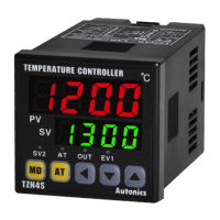
When power is supplied, whole display parts ash for 1 sec. Afterwards, model name and input sensor type
will be ash twice and then in enters into RUN mode.
※
1: C (TT): Same temperature sensor as former W5 (TT)
※
2: G (TT): Same temperature sesnor as former W (TT)
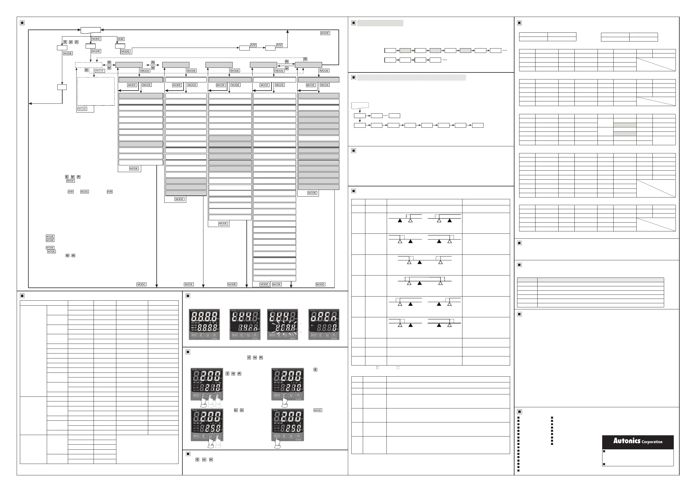
You can set the temperature to control with
, ,
keys.
Set range is within SV low-limit value [
L-SV
] to SV high-limit value [
H-SV
].
Ex) In case of changing set temperature from 210
℃
to 250
℃
Press any key among
, ,
in RUN mode
to enter into SV setting
mode.
Last digit (10
0
digit) on
SV display part ashes.
※
Condition of re-applied standby sequence for standby sequence 1, alarm latch and standby sequence 1: Power ON
Condition of re-applied standby sequence for standby sequence 2, alarm latch and standby sequence 2: Power ON,
changing set temperature, alarm temperature [
AL1
,
AL2
] or alarm operation [
AL-1
,
AL-2
], switching STOP mode
to RUN mode.
※
H: Alarm output hysteresis[
A .HY
]
※
Shaded parameters are for the heating&cooling model.
●Alarm option
●Alarm operation
Press
,
key to raise
or lower the set value.
Press key to move digit.
(10
0
→ 10¹→
10²→10³→ 10
0
)
Press
key to save
the set value.
If there is no additional
key operations in 3 sec,
the changed SV is
automatically saved.
※
Hold the key over 2 sec in RUN mode to enter into setting mode.
※
Hold the key for 1.5 sec while in setting mode to move to other
parameter group.
※
Hold the key over 3 sec while in setting mode to return to RUN mode.
※
Press the key at the lowest level of parameter to move parameter
group screen and press , key to move to other parameter group.
※
If there is no additional key operation within 30 sec after entering into setting
mode, it will be automatically returned to RUN mode and previous set value
will be remained.
※
The not-shaded parameters may not be displayed by other parameters
setting, parameter mask setting.
This function is able to hide unnecessary parameters to user environment or less frequently used parameters in
parameter group. You can set this in the integrated device management program (DAQmaster).
Masked parameters are not only displayed. The set value of masked parameters are applied.
For more information, refer to the DAQMaster user manual.
Visit our website (www.autonics.com) to download the DAQmaster program and the user manual.
For the detail information and instructions, please refer to user manual and user manual for communication,
and be sure to follow cautions written in the technical descriptions (catalog, homepage).
Visit our homepage (www.autonics.com) to download manuals.
DAQMaster is a comprehensive device management software for setting parameters and monitoring
processes. DAQMaster can be downloaded from our website at www.autonics.com.
Parameter Factory default
SV 0
Parameter
Factory default
Parameter
Factory default
Parameter
Factory default
Parameter
Factory default
R-S RUN AL!H 1550 AL#H 1550 SV-3 0000
SV-N SV-0 AL@L 1550 SV-0 0000
CT-A )0 AL@H 1550 SV-1 0000
AL!L 1550 AL#L 1550 SV-2 0000
Parameter
Factory default
Parameter
Factory default
Parameter
Factory default
Parameter
Factory default
AT OFF H-D 0000 hOST 000 RAMU 000
H-P 01)0 C-D 0000 cHYS 002 RAMD 000
C-P 01)0 DB 0000 cOST 000 rUNT MIN
H-I 0000 REST 05)0 L-MV `0)0
C-I 0000 hHYS 002 H-MV 10)0
Parameter
Factory default
Parameter
Factory default
Parameter
Factory default
Parameter
Factory default
IN-T KCaH H-SC 10)0
O-FT
HEAT O!SR STND
UNIT ?C dUNT ?/O H-C O!MA 4-20
L-RG 0)00 IN-B 0000
C-MD
PID OUT2 CURR
H-RG 1)00 MAvF 00)1 pP O@MA 4-20
DOT )0 L-SV -200 AtT TUN1 H-T
02)0
(Relay)
00@0
(SSR)
L-SC 00)0 H-SV 1350 OUT1 CURR C-T
Parameter
Factory default
Parameter
Factory default
Parameter
Factory default
Parameter
Factory default
AL-1 DVCC A@N NO LBaT 0000 BPS 96
AL!T AL-A A@ON 0000 LBaB 002 PRTY NONE
A!HY 001 A@OF 0000 AoM1 PV STP 2
A!N NO AL-3 OFF FsL1 -200 RSWT 20
A!ON 0000 AL#T AL-A FsH1 1350 COMW EnA
A!OF 0000 A#HY 001 AoM2 PV
AL-2 ]]DV A#N NO FsL2 -200
AL@T AL-A A#ON 0000 FsH2 1350
A@HY 001 A#OF 0000 ADRS 01
Parameter
Factory default
Parameter
Factory default
Parameter
Factory default
Parameter
Factory default
MtSV 1 PrMV 00)0 LcSV OFF LcPS OFF
DI-K STOP ErMV 00)0 LcP1 OFF PWD 0000
DI-1 OFF StMV 00)0 LcP2 OFF
DI-2 OFF StAL CONT LcP3 OFF
ItMV AUTO USER STND LcP4 OFF
Parameter Factory default
PASS 0001
This function is able to set the frequently used parameters to the user parameter group. You can quickly and
easily set parameter settings. User parameter group can have up to 30 parameters in the integrated device
management program (DAQMaster).
For more information, refer to the DAQMaster user manual.
Visit our website (www.autonics.com) to download the DAQmaster program and the user manual.
Auto-tuning measures the control subject's thermal characteristics and thermal response rate, and then
determines the necessary PID time constant. Application of the PID time constant realizes fast response and
high precision temperature control. (when setting control type [
C-MD
] is set as
PID
, it is displayed.)
Set [
AT
] parameter to [
ON
] in parameter 2 group to start auto-tuning. To stop auto-tuning, change the set as [
OFF
].
(It maintains P, I, D values of before auto-tuning.)
If sensor break error [
OPEN
] occurs during auto-tuning, it stops this operation. If the measured temperature is
over or below the input range, it operates continuously.
During auto-tuning operation, whole parameters are only available to check.
Mode Name Alarm operation Description
OFF
- -
No alarm output
DVCC
Deviation
high-limit
alarm
If deviation between PV and SV
as high-limit is higher than set
value of deviation temperature,
the alarm output will be ON.
]]DV
Deviation
low-limit
alarm
If deviation between PV and SV
as low-limit is higher than set
value of deviation temperature,
the alarm output will be ON.
]DVC
Deviation
high/low-limit
alarm
If deviation between PV and
SV as high/low-limit is higher
than set value of deviation
temperature, the alarm output
will be ON.
CDV]
Deviation
high/low-limit
reserve alarm
If deviation between PV and
SV as high/low-limit is lower
than set value of deviation
temperature, the alarm output
will be OFF.
PVCC
Absolute
value high-
limit alarm
If PV is higher than the absolute
value, the output will be ON.
]]PV
Absolute
value low-limit
alarm
If PV is lower than the absoulte
value, the output will be ON.
LBA
Loop break
alarm
-
It will be ON when it detects
loop break.
SBA
Sensor break
alarm
-
It will be ON when it detects
sensor disconnection.
HBA
Heater break
alarm
-
It will be ON when CT detects
heater break.
Mode Name Description
AL-A
Standard alarm
If it is an alarm condition, alarm output is ON. If it is a clear alarm condition, alarm output is OFF.
AL-B
Alarm latch If it is an alarm condition, alarm output is ON and maintains ON status.
AL-C
Standby
sequence 1
First alarm condition is ignored and from second alarm condition, standard alarm
operates. When power is supplied and it is an alarm condition, this rst alarm
condition is ignored and from the second alarm condition, standard alarm operates.
AL-D
Alarm latch
and standby
sequence 1
If it is an alarm condition, it operates both alarm latch and standby sequence. When
power is supplied and it is an alarm condition, this rst alarm condition is ignored and
from the second 1alarm condition, alarm latch operates.
AL-E
Standby
sequence 2
First alarm condition is ignored and from second alarm condition, standard alarm
operates. When re-applied standby sequence and if it is alarm condition, alarm output
does not turn ON. After clearing alarm condition, standard alarm operates.
AL-F
Alarm latch
and standby
sequence 2
Basic operation is same as alarm latch and standby sequence1. It operates not only
by power ON/OFF, but also alarm set value, or alarm option changing. When re-
applied standby sequence and if it is alarm condition, alarm output does not turn ON.
After clearing alarm condition, alarm latch operates.
The above is masking auto tuning [
AT
], cooling proportional band [
C-P
], cooling integral time [
C-1
],
cooling derivative time [
C-D
] parameters in parameter 2 group.
The above is setting user parameter group in the DAQMaster with alarm output 1 low-limit value [
AL!L
], alarm output 1
high-limit value [
AL!H
], SV-0 set value [
SV-0
] parameter of parameter 1 group, heating hysteresis[
hHYS
],
cooling hysteresis [
cHYS
] parameters of parameter 2 group, input correction [
IN-B
] parameter of parameter 3
group, alarm output 1 hysteresis [
A!HY
], alarm output 2 hysteresis [
A@HY
] parameters of parameter 4 group.
Before applying mask
After applying mask
PASS
Run mode
PASS
Alarm output2 low-limit set value[
AL@L
]
SV-0 set value[
SV-0
]
Alarm output1 low-limit set value[
AL!L
]
Alarm output3 low-limit set value[
AL#L
]
SV-2 set value[
SV-2
]
Heater current monitoring[
CT-A
]
Alarm output2 high-limit set value[
AL@H
]
SV-1 set value[
SV-1
]
Alarm output1 high-limit set value[
AL!H
]
Alarm output3 high-limit set value[
AL#H
]
SV-3 set value[
SV-3
]
Heating proportional band[
H-P
]
Auto-tuning RUN/STOP[
AT
]
Heating derivative time[
H-D
]
Heating hysteresis[
hHYS
]
Heating integral time[
H-I
]
Dead_overlap band[
DB
]
Cooling hysteresis[
cHYS
]
MV high-limit[
H-MV
]
RAMP time unit[
rUNT
]
Cooling proportional band[
C-P
]
Cooling derivative time[
C-D
]
Heating OFF offset[
hOST
]
MV low-limit[
L-MV
]
RAMP-down change rate[
RAMD
]
Cooling integral time[
C-I
]
Manual reset[
REST
]
Cooling OFF offset[
cOST
]
RAMP-up change rate[
RAMU
]
Sensor temperature unit[
UNIT
]
Input type[
IN-T
]
Alarm output1 option[
AL!T
]
Alarm output1operation mode[
AL-1
]
Alarm output3 option[
AL#T
]
Low-limit scale value[
L-SC
] Alarm1 OFF delay time[
A!OF
]
Alarm 3 OFF delay time[
A#OF
]
Input digital lter[
MAvF
]
Auto-tuning mode[
AtT
]
Alarm 2 N.O./N.C.[
A@N
]
Trans. output 1 low-limit value[
FsL1
]
Analog high-limit input value[
H-RG
]
Alarm1 N.O./N.C.[
A!N
]
Alarm 3 N.O./N.C.[
A#N
]
Display unit[
dUNT
] Alarm output2 option[
AL@T
]
LBA band[
LBaB
]
SV high-limit[
H-SV
]
OUT1 SSR drive output type[
O!SR
]
Alarm 2 OFF delay time[
A@OF
]
Analog trans. output 2 mode[
AoM2
]
Analog low-limit input value[
L-RG
]
Alarm output1 hysteresis[
A!HY
]
Alarm output3 hysteresis[
A#HY
]
High-limit scale value[
H-SC
]
Alarm output2 operation mode[
AL-2
]
LBA time[
LBaT
]
SV low-limit[
L-SV
]
OUT1 control output selection[
OUT1
]
Alarm 2 ON delay time[
A@ON
]
Trans. output 1 high-limit value[
FsH1
]
Scaling decimal point[
DOT
] Alarm1 ON delay time[
A!ON
]
Alarm 3 ON delay time[
A#ON
]
Input correction[
IN-B
]
Control type[
C-MD
]
Alarm output2 hysteresis[
A@HY
]
Analog trans. output 1 mode[
AoM1
]
Control output operation mode[
O-FT
]
OUT1 current output range[
O!MA
]
OUT2 control output selection[
OUT2
]
OUT2 current output range[
O@MA
]
Heating control time[
H-T
]
Cooling control time[
C-T
]
Alarm output3 operation mode[
AL-3
]
Trans. output 2 low-limit value[
FsL2
]
Trans. output 2 high-limit value[
FsH2
]
Comm. address[
ADRS
]
Comm. speed[
BPS
]
Comm. parity bit[
PRTY
]
Comm. stop bit[
STP
]
Comm. response waiting time[
RSwT
]
Comm. write[
COMW
]
3 sec
3 sec
①
③
②
④
①
Whole display part
②
Model type display
③
Input type display twice
④
Run mode
3 sec
3 sec
1.5 sec
1.5 sec
Heating MV
Monitoring
Cooliing MV
Monitoring
SV
100
℃
OFF
OFF
OFFOFF
OFF
OFF OFF
OFF OFF
OFF
OFFONON
ON ON
ON
ON ON
ONON
ON ON
HH
H H
HH
H H
H H
HH
PV
90
℃
PV
90
℃
PV
90
℃
PV
90
℃
PV
90
℃
High deviation: Set as 10
℃
Low deviation: Set as 10
℃
Absolute-value: Set as 90
℃
Absolute-value: Set as 90
℃
Low deviation : Set as 10
℃
, High deviation : Set as 20
℃
Low deviation : Set as 10
℃
, High deviation : Set as 20
℃
High deviation: Set as -10
℃
Low deviation: Set as -10
℃
Absolute-value: Set as 110
℃
Absolute-value: Set as 110
℃
PV
110
℃
SV
100
℃
SV
100
℃
SV
100
℃
SV
100
℃
SV
100
℃
PV
120
℃
PV
120
℃
PV
90
℃
SV
100
℃
SV
100
℃
SV
100
℃
SV
100
℃
PV
110
℃
PV
110
℃
PV
110
℃
1.5 sec
1.5 sec
1.5 sec
2 sec
3 sec
3 sec
Digital input key[
DI-K
]
Multi SV[
MtSV
]
Manual control, preset MV[
PrMV
]
User level[
USER
]
Parameter 3group lock[
LcP3
]
DI-2 input terminal function[
DI-2
]
Control stop, MV[
StMV
]
Parameter 1group lock[
LcP1
]
Parameter 5group lock[
LcP5
]
DI-1 input terminal function[
DI-1
]
Sensor error, MV[
ErMV
]
SV setting lock[
LcSV
]
Parameter 4group lock[
LcP4
]
Manual control, initial MV[
ItMV
]
Control stop, alarm output[
StAL
]
Parameter 2group lock[
LcP2
]
Password setting[
PWD
]
PAR2 AT H-P C-P H-I C-I H-D C-D
PAR2 H-P H-I H-D
●SV setting group [
SV
]
●Parameter 1 group [
PAR1
]
●Parameter 2 group [
PAR2
]
●Parameter 3 group [
PAR3
]
●Parameter 4 group [
PAR4
]
●Parameter 5 group [
PAR5
]
●Password input parameter
Run mode
AL!L AL!H SV-0 hHYS cHYS IN-B A!HY A@HY
PARU PAR1 PAR2
Item Minimum specications
System IBM PC compatible computer with Pentium
Ⅲ
or above
Operations Windows 98/NT/XP/Vista/7/8/10
Memory 256MB+
Hard disk 1GB+ of available hard disk space
VGA Resolution: 1024×768 or higher
Others RS232C serial port (9-pin), USB port
1.
Follow instructions in 'Cautions during Use'. Otherwise, It may cause unexpected accidents.
2. Check the polarity of the terminals before wiring the temperature sensor.
For RTD temperature sensor, wire it as 3-wire type, using cables in same thickness and length.
For thermocouple (CT) temperature sensor, use the designated compensation wire for extending wire.
3. Keep away from high voltage lines or power lines to prevent inductive noise.
In case installing power line and input signal line closely, use line filter or varistor at power line and shielded
wire at input signal line.
Do not use near the equipment which generates strong magnetic force or high frequency noise.
4. Do not apply excessive power when connecting or disconnecting the connectors of the product.
5. Install a power switch or circuit breaker in the easily accessible place for supplying or disconnecting the
power.
6. Do not use the unit for other purpose (e.g. voltmeter, ammeter), but temperature controller.
7. When changing the input sensor, turn off the power first before changing.
After changing the input sensor, modify the value of the corresponding parameter.
8. 24VAC, 24-48VDC power supply should be insulated and limited voltage/current or Class 2, SELV power
supply device.
9. Do not overlapping communication line and power line.
Use twisted pair wire for communication line and connect ferrite bead at each end of line to reduce the effect
of external noise.
10. Make a required space around the unit for radiation of heat.
For accurate temperature measurement, warm up the unit over 20 min after turning on the power.
11. Make sure that power supply voltage reaches to the rated voltage within 2 sec after supplying power.
12. Do not wire to terminals which are not used.
13. This unit may be used in the following environments.
①
Indoors (in the environment condition rated in 'Specifications')
②
Altitude max. 2,000m
③
Pollution degree 2
④
Installation category II
Photoelectric Sensors Temperature Controllers
Fiber Optic Sensors Temperature/Humidity Transducers
Door Sensors SSRs/Power Controllers
Door Side Sensors Counters
Area Sensors Timers
Proximity Sensors Panel Meters
Pressure Sensors Tachometer/Pulse (Rate) Meters
Rotary Encoders Display Units
Connector/Sockets Sensor Controllers
Switching Mode Power Supplies
Control Switches/Lamps/Buzzers
I/O Terminal Blocks & Cables
Stepper Motors/Drivers/Motion Controllers
Graphic/Logic Panels
Field Network Devices
Laser Marking System (Fiber, CO
₂
, Nd: YAG)
Laser Welding/Cutting System
http://www.autonics.com
HEADQUARTERS:
18, Bansong-ro 513beon-gil, Haeundae-gu, Busan,
South Korea, 48002
TEL: 82-51-519-3232
E-mail:
sales@autonics.com
DRW170598A A
Input type Decimal point Display Input range (
℃
) Input range (
℉
)
Thermocouple
K (CA)
1
KCaH
-200 to 1350 -328 to 2463
0.1
KCaL
-199.9 to 999.9 -199.9 to 999.9
J (IC)
1
JIcH
-200 to 800 -328 to 1472
0.1
JIcL
-199.9 to 800.0 -199.9 to 999.9
E (CR)
1
ECrH
-200 to 800 -328 to 1472
0.1
ECrL
-199.9 to 800.0 -199.9 to 999.9
T (CC)
1
TCcH
-200 to 400 -328 to 752
0.1
TCcL
-199.9 to 400.0 -199.9 to 752.0
B (PR) 1
B PR
0 to 1800 32 to 3272
R (PR) 1
R PR
0 to 1750 32 to 3182
S (PR) 1
S PR
0 to 1750 32 to 3182
N (NN) 1
N NN
-200 to 1300 -328 to 2372
C (TT)
※
1
1
C TT
0 to 2300 32 to 4172
G (TT)
※
2
1
G TT
0 to 2300 32 to 4172
L (IC)
1
LIcH
-200 to 900 -328 to 1652
0.1
LIcL
-199.9 to 900.0 -199.9 to 999.9
U (CC)
1
UCcH
-200 to 400 -328 to 752
0.1
UCcL
-199.9 to 400.0 -199.9 to 752.0
Platinel II 1
PLII
0 to 1390 32 to 2534
RTD
Cu 50Ω 0.1
CU 5
-199.9 to 200.0 -199.9 to 392.0
Cu 100Ω 0.1
CU10
-199.9 to 200.0 -199.9 to 392.0
JPt 100Ω
1
JPtH
-200 to 650 -328 to 1202
0.1
JPtL
-199.9 to 650.0 -199.9 to 999.9
DPt 50Ω 0.1
DPt5
-199.9 to 600.0 -199.9 to 999.9
DPt 100Ω
1
DPtH
-200 to 650 -328 to 1202
0.1
DPtL
-199.9 to 650.0 -199.9 to 999.9
Nickel 120Ω 1
NI12
-80 to 200 -112 to 392
Analog
Voltage
0-10V
AV1
-1999 to 9999
(Display point will be changed
according to decimal point position.)
0-5V
AV2
1-5V
AV3
0-100mV
AMV1
Current
0-20mA
AMA1
4-20mA
AMA2
Parameter Reset
Press
+ +
to reset all parameters in memory to default value.
Set [
INIT
] parameter to '
YES
' to reset all parameters.
In case password function is on, it is required to enter valid password to reset parameters.
Password is also reset.
 Loading...