Do you have a question about the Autonics TK4L and is the answer not in the manual?
Explains symbols used in the manual, including Note, Warning, Caution, and Annotation marks.
Details the key features and capabilities of the TK series temperature controllers.
Lists and illustrates the physical components and optional accessories included with the controller.
Presents the different models available in the TK series, outlining their specifications.
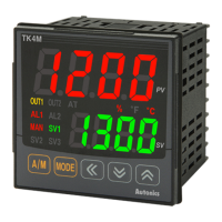
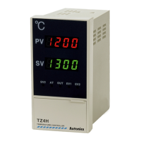
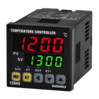
Identifies and describes the function of each display element and control key on the controller.
Provides detailed technical specifications, including power, display, input types, and output ratings.
Provides guidance and diagrams for the physical installation of the controller.
Illustrates the internal and external wiring connections for the TK4S-Series controller.
Details important precautions to follow during wiring to prevent damage or malfunction.
Guides the user through the initial power-up sequence and the controller's startup display.
Explains fundamental operations for controlling the controller, including parameter and SV settings.
Provides a chart referencing controller parameters, their groups, and memory addresses.
Covers configuration of input types, ranges, and related settings for temperature sensors.
Details the configuration of control output modes, including heating, cooling, and MV settings.
Explains temperature control methods such as PID, On/Off, and Heating/Cooling.
Covers the configuration of alarm outputs, modes, options, hysteresis, and specific alarm types.
Details communication settings, including unit address, BPS, parity, stop bits, and write permissions.
Describes parameters related to the SV group, including Set Value and Digital Input Key execution.
Lists and describes parameters found in Setting Group PAR1, covering Run/Stop, alarms, and SV settings.
Details parameters within Setting Group PAR2, including auto-tuning, proportional band, and hysteresis settings.
Outlines parameters in Setting Group PAR3, covering input types, control modes, and output settings.
Lists parameters for Setting Group PAR4, focusing on alarm modes, hysteresis, and communication settings.
Describes parameters in Setting Group PAR5, including Multi SV, digital input, password, and lock settings.
Provides a general introduction to DAQMaster, Autonics' device management program.
Highlights the key features of DAQMaster, such as multiple device support and data logging.
| Model | TK4L |
|---|---|
| Mounting | Panel mount |
| Input Type | Thermocouple, RTD |
| Output Type | Relay, Current |
| Control Method | PID, On-Off |
| Display Type | 4-digit LED |
| Temperature Range | Depends on input type (e.g., -200 to 2300°C for thermocouples) |
| Power Supply | AC 100~240V, 50/60Hz |
| Operating Temperature | -10 to 50℃ |
| Accuracy | ±0.3% FS ±1 digit |
| Setting Resolution | 0.1°C or 1°C (selectable) |
| Communication | RS-485 (optional) |
| Ambient Temperature | -10 to 50℃ |
| Storage Temperature | -20 to 60℃ |