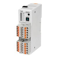
TM Series
Parts description
※
1
※
2
※
3
※
4
※
5
[Removal method]
①
②
[Installation method]
①
②
※
Make sure to install the unit vertically to the ground.
( O )
( X )
3. PC loader port(Port A)
4. Communication address setting switch(SW1)
5. Communication address group change switch(SW2)
6. Lock switch
7. Rail Lock
8. END Cover
9. Power supply / communications connector(PortB)
※
※
※
※
※
1. Display LED(TM2 Series)
2. Display LED(TM4 Series)
※
1
※
2
※
3
TM2 Series
TM4 Series
DIN Rail Installation
4
4
1
5
2
6
6
3
7
7
8
8
9
9
3
①
②
①
②