Autostacker™ Parking Lift 27 P/N 5900248 — Rev. B — May 2021
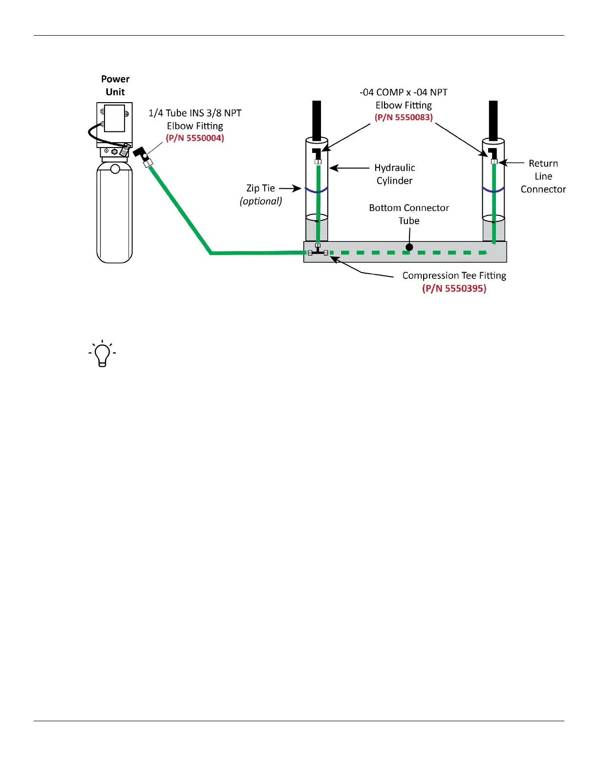
The following diagram shows how the Return Lines should be arranged.
Not drawn to scale. Sample Power Unit shown. Power Unit goes inside the Console. Not all
components shown for clarity. Return Line is routed through the Bottom Connector Tube.
Tip If you want, you can use zip ties (also called cable ties, not supplied) to hold the Return
Lines in place once they are connected.
To connect the Return Line:
1. Attach an Elbow Fitting to one of the two Return Line Ports on the Power Unit.
Use Thread Sealant with NPT Threads only.
There are two Hydraulic Return Ports on the Power Unit; they work the same, so choose the one
that is best for you.
You only need to use one, not both
. They are shown in the drawing in
Connect the Power Unit.
2. Attach an Elbow Fitting to both Return Line Connectors near the top of each Hydraulic Cylinder.
Use Thread Sealant with NPT Threads only.
3. Locate a Tee Fitting and put it near the bottom of the Hydraulic Cylinder closest to the Console.
4. Locate the Return Line tubing and cut the appropriate lengths for each of the three Return Line
segments.
5. Connect a Return Line between the Power Unit and the Tee Fitting.
6. Connect a Return Line between the Tee Fitting and the Return Line connector on the Hydraulic
Cylinder nearest the Console.
7. Connect the final Return Line to the Tee Fitting, route it through the Bottom Connector Tube, then
connect it to the Return Line connector on the Hydraulic Cylinder furthest from the Console.