EasyManua.ls Logo

Autotrol Logix 740 - User Manual

Autotrol Logix 740
67 pages
Print Icon
To Next Page IconTo Next Page
Loading...
For Sales & Service questions please
contact your dealer:
Your local dealer is:
740/760 Control
255 and Performa Series Valves
(268, 268FA)
Operation Manual
Produced with a Trial Version of PDF Annotator - www.PDFAnnotator.com

Questions and Answers

  • J
    John CainSep 3, 2025
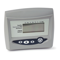
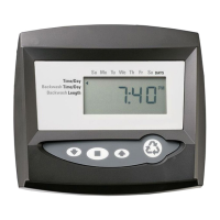
    How to troubleshoot ERR 2 on Autotrol Logix 740 Control Unit?
    • V
      Victoria DiazSep 3, 2025
      If the Autotrol Control Unit displays ERR 2, the controller power doesn't match 50 or 60 Hz. Disconnect and reconnect the power. If the problem persists, obtain the appropriate controller or AC adapter for either 50 or 60 Hz power.
  • M
    Michael BentleySep 18, 2025
    Why is my Autotrol Logix 740 leaking hard water after regeneration?
    • T
      thomasdianaSep 18, 2025
      If you're experiencing hard water leakage after regeneration with your Autotrol Control Unit, it could be due to several reasons. First, the regeneration might be improper; repeat the regeneration after ensuring the correct regenerant dosage was set. Second, there might be leaking of the external bypass valve, so replace the bypass valve. Third, the O-ring around the riser pipe might be damaged, so replace the O-ring. Finally, the capacity might be incorrect; verify the appropriate regenerant amount and system capacity.
  • D
    dawn43Sep 16, 2025
    Why does Autotrol Control Unit backwash at an excessively high rate?
    • R
      Robin CruzSep 16, 2025
      If the Autotrol Control Unit backwashes or purges at an excessively low or high rate, it could be due to using an incorrect drain controller, so replace it with the correct size controller. Another cause may be foreign matter affecting valve operation, so remove the drain controller and clean the ball and seat.
  • C
    Candice RileySep 15, 2025
    Why is there no conditioned water after regeneration in my Autotrol Control Unit?
    • M
      Mary BrennanSep 15, 2025
      If there is no conditioned water after regeneration with your Autotrol Control Unit, it could be due to a few reasons. First, check if there is no regenerant in the regenerant tank and add regenerant to the regenerant tank. Second, the injector might be plugged, so clean the injector and screen. Third, the air check valve might be closing prematurely, so put the control momentarily into brine/slow rinse, C2. Replace or repair air check if needed.
  • N
    Nicole LinSep 13, 2025
    What to do if Autotrol Control Unit has flowing water at drain after regeneration?
    • C
      Curtis RamirezSep 13, 2025
      If you have flowing or dripping water at the drain or brine line after regeneration with your Autotrol Control Unit, it may be because the valve stem return spring is weak and needs replacement. Another cause may be that debris is preventing the valve disc from closing, so remove the debris.
  • C
    Cory VincentSep 12, 2025
    Why won't my Autotrol Logix 740 Control Unit valve draw brine?
    • P
      Patricia ScottSep 12, 2025
      If the Autotrol Control Unit valve won't draw brine, it could be due to low water pressure, so set the pump to maintain 20 psi at the softener. It could also be due to a restricted drain line, so change the drain to remove the restriction. Another reason may be that the injector is plugged, so clean the injector and screen. Finally, the air check valve may be closing prematurely on the 255 valve or brine pickup tube. Put the control momentarily into brine/slow rinse, C2. Replace or repair air check if needed.
  • M
    Mike KerrSep 10, 2025
    Why is my Autotrol Logix 740 Control Unit drawing regenerant intermittently?
    • R
      Ryan WadeSep 12, 2025
      If you're experiencing intermittent or irregular regenerant draw with your Autotrol Control Unit, it could be due to low water pressure. Set the pump to maintain 20 psi at the conditioner. Another possible cause is a defective injector, which would require replacement.
  • J
    Joshua LeeSep 8, 2025
    Why is my Autotrol Control Unit using more or less salt than the regenerant setting?
    • J
      jorgeyangSep 8, 2025
      If the Autotrol Control Unit is using more or less salt than the regenerant setting, there might be foreign matter in the valve causing incorrect flow rates. Remove the brine control and flush out any foreign matter. Advance the control to brine/slow rinse, C2, to clean the valve, then position the control to “fast rinse, C7” to remove regenerant from the tank.
  • T
    Tammy KingSep 6, 2025
    What causes brine tank overflow in Autotrol Logix 740 Control Unit?
    • J
      Jacob KennedySep 7, 2025
      If you experience a brine tank overflow with the Autotrol Control Unit, it could be due to: 1. Uncontrolled brine refill flow rate. Remove brine control to clean ball and seat. 2. Air leak in brine line to air check. Check all connections in brine line for leaks. Refer to instructions. 3. Drain control clogged with resin or other debris. Clean drain control.
  • C
    Claudia MillerAug 21, 2025
    What to do if Autotrol Logix 740 displays ERR 3?
    • W
      wellsjohnAug 21, 2025
      If the Autotrol Control Unit displays ERR 3, it means the controller can't determine the camshaft's position and the camshaft should be rotating to find Home position. Wait two minutes for the controller to return to the Home position; an hourglass should flash on the display, indicating the motor is running. If the camshaft isn't turning, check the motor connection, wire harness connections, optical sensor, and motor gear engagement. If the camshaft turns for more than five minutes, verify the optical sensor and camshaft connections, and check for obstructions in the cam slots. If problems persist, replace the wire harness, motor, optical sensor, and controller in that order.

Summary

LOGIX SERIES INSTALLER QUICK-START SHEET

Initial Power-up Procedures

Guides initial camshaft rotation and self-test sequence upon power connection.

Step-by-Step Initial Setup

Covers system size, time, day, regen time, and capacity programming.

Manual Regeneration and Cycle Control

Explains initiating, advancing, and canceling regeneration cycles.

Control Reset and Reprogramming

Steps for resetting the control to default settings.

MANUAL OVERVIEW

Guide to Manual Usage

Explains how to effectively use the manual and installer prerequisites.

Understanding Manual Icons

Defines warning and note icons used throughout the document.

EQUIPMENT INSTALLATION

Installation Safety Warnings

Crucial electrical and mechanical safety precautions for installation.

System Regeneration Cycle Overview

Details the seven cycles of a typical water conditioner regeneration.

Valve Component Identification

Illustrates and names key parts of 255 and Performa valve bodies.

Site Selection Criteria

Essential conditions for choosing an appropriate installation location.

Water and Drain Line Connections

Guidelines for connecting water supply, bypass, and drain lines.

Regenerant and Electrical Connections

Procedures for connecting the regenerant line and electrical power supply.

Valve Camshaft and Disc Operation

Explains camshaft functionality and valve disc mechanics during operation.

SYSTEM DISINFECTION

Water Conditioner Disinfection Methods

Explains why and how to disinfect water conditioners using hypochlorite.

CONTROL MODEL IDENTIFICATION

Determining 740 or 760 Control Type

How to identify the specific control model via a valve label.

GENERAL 700 SERIES CONTROLLER OPERATIONS

Controller Features Overview

Details memory retention, motor operation, and power configurations.

Variable Reserve Functionality

Explains the automatic adjustment of reserve based on water usage.

CONTROLLER DISPLAY AND INTERFACE

Understanding Display Icons

Explains the meaning and function of various controller display icons.

Keypad Button Functions

Identifies and describes the operation of each button on the controller keypad.

Regeneration Mode Operations

Covers manual and automatic regeneration initiation and cycle control.

Initial Power-Up and Setup Steps

Guides through initial power-up, startup procedures, capacity, and hardness settings.

PLACING CONDITIONER INTO OPERATION

Conditioner and FA Filter Start-Up Guide

Step-by-step instructions for bringing the conditioner online after setup.

PROGRAMMING FOR 5-CYCLE FILTER APPLICATIONS

Manganese Greensand System Setup

Specific programming for manganese greensand filters, including sizing and settings.

Calculating Regeneration Frequency

Method for determining days between regenerations based on media capacity.

Demand-Based Regeneration Configuration

Steps to set up on-demand regeneration for iron removal using 760 controllers.

ADVANCED 700 SERIES PROGRAMMING

Programming Overview and History Access

Explains accessing advanced settings, viewing history values, and resetting the control.

Level II Professional Programming

Details advanced programming menus intended for dealer use only.

VALVE SERVICE AND MAINTENANCE

Cover and Module Service

Instructions for removing/installing the valve cover and electronic control module.

Drive Motor and Optical Sensor Maintenance

Procedures for servicing the drive motor and optical sensor.

Camshaft and Spring Service

Steps for removing/installing the camshaft and valve disc spring.

Microswitch and Optional Components

Installation of microswitches and optional relays, terminal blocks, transformers.

Top Plate and Valve Disc Replacement

Guidance on removing/installing the top plate and valve discs.

PARTS AND ACCESSORIES REFERENCE

Valve Component Identification Views

Exploded views showing parts for 255 and Performa valves.

255 Valve Parts List

Detailed list of part codes and descriptions for the 255 valve.

Performa Valve Parts List

Detailed list of part codes and descriptions for Performa valves.

Logix 700 Series Controller Parts

List of part codes and descriptions for Logix 700 series controllers.

TROUBLESHOOTING GUIDE

700 Series Controller Issues

Common problems, causes, and solutions for the 700 series controller.

Autotrol Logix 740 Specifications

General IconGeneral
ModelLogix 740
CategoryControl Unit
DisplayLCD
ProgrammingUser-programmable
Valve CompatibilityCompatible with Autotrol valves
Cycle TimeAdjustable
MountingValve mounted

Related product manuals