OUTDOOR UNIT INSTALLATION
4
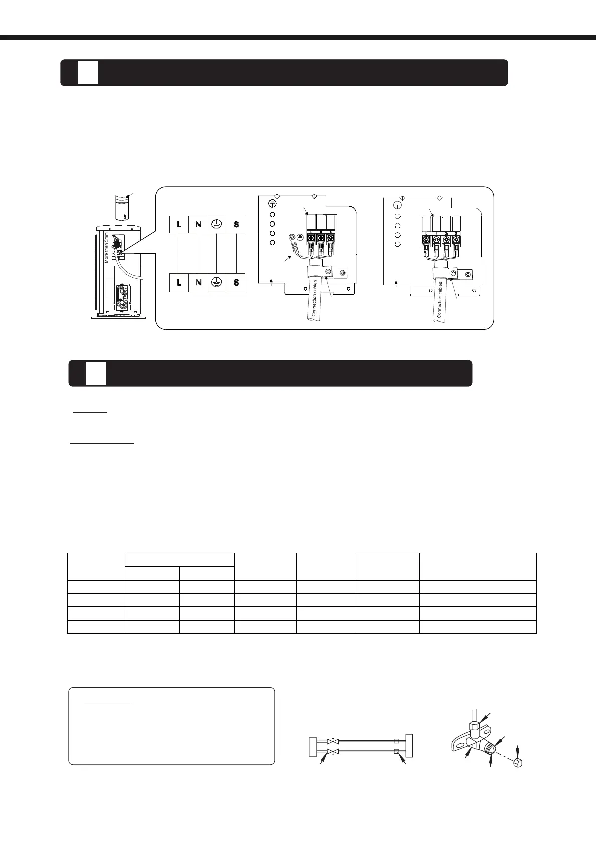
1. Remove the electrical control board cover from the outdoor unit by loosening the screw.
2. Connect the connective cables to the terminals as identified with their respective matched numbers
on the terminal block of indoor and outdoor units.
3. Secure the cable onto the control board with the cord clamp.
4. To prevent the ingress of water, form a loop of the connective cable as illustrated in the installation
diagram of indoor and outdoor units.
5. Insulate unused cords (conductors) with PVC-tape. Process them so they do not touch any electrical
or metal parts.
CONNECT THE CABLE TO THE OUTDOOR UNIT
Open the valve stem until it hits against
the stopper. Do not try to open it further.
Securely tighten the valve stem cap with
a spanner or the like.
.
.
.
Flare nut
Stopper
Cap
Valve body
Valve stem
F
or the R410A refrigerant model, make sure the refrigerant added into air conditioner is liquid
form in any cases.
When relocating the unit to another place, using vacuum pump to perform evacuation.
.
.
.
.
The indoor unit and tubing between the indoor and outdoor unit must be leak tested and evacuated
to remove any noncondensables and moisture from the system.
Check that each tube(both liquid and gas side tubes) between the indoor and outdoor units have
been properly connected and all wiring for the test run has been completed.
Pipe length and refrigerant amount:
Outdoor
unit
Indoor
unit
Refrigerant
Packed valve
Flare nut
Gas side
Liquid side
A
C
D
B
1. Air purging
CAUTION
NOTE:
Connective pipe length will affect the capacity and energy efficiency of the unit. The
nominal efficiency is tested basing on the pipe length of 5 meters.
A
IR PURGING AND TEST OPERATION
5
Co ver
Electric bracket
Electric bracket
Grou nded w i re
Pr e ssing b oa rd
Pr e ssing b oa rd
Te rm inal board
Ter minal board
Indoor Unit
Outdoor Unit
Dimensions, pipes lenght and additional refrigerant charge:
The unit comes preloaded for liquid pipe lengths less than 5 m.
54
1/4" 3/8" 20 m 10 m 5 m X = 20 gr/m
1/4" 3/8" 20 m 10 m 5 m X = 25 gr/m
1/4" 1/2" 25 m 15 m 5 m X = 30 gr/m
3/8" 5/8" 25 m 15 m 5 m X = 40 gr/m
09
12
18
24
Additional Charge
R410a = (Total Lenght - 5 )* X
Model
Pipe
Lenght
Max. Pipe
Max. Drop
Height
Preload
Líquid
Gas
 Loading...