OUTDOOR UNIT INSTALLATION
Install
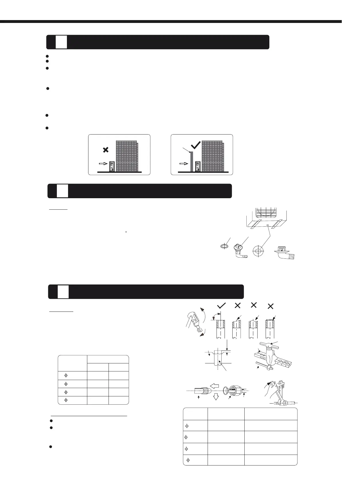
the outdoor unit on a rigid base to prevent increasing noise level and vibration.
Determine the air outlet direction where the discharged air is not blocked.
In the case that the installation place is exposed to strong wind such as a seaside, make
sure the fan operating properly by putting the unit lengthwise along the wall or using a dust
or shield plates.
Specially in windy area, install the unit to prevent the admission of wind. If need suspending
installation, the installation bracket should accord with technique requirement in the
installation bracket diagram. The installation wall should be solid brick, concrete or the same
intensity construction, or actions to reinforce, damping supporting should be taken.
The connection between bracket and wall, bracket and the air conditioner should be firm,
stable and reliable.
Be sure there is no obstacle which block radiating air.
Strong
wind
Strong
wind
Barrier
Incorrect
Correct
Seal
Drain
joint
Base
pan hole
of outdoor unit
(A)
(B)
The
drain joint is slightly different according to the
different outdoor unit.
For the drain joint with the seal(Fig.A), first fit the seal onto
the drain joint, then insert the drain joint into the base pan
hole of outdoor unit, rotate 90 to securely assemble them.
To install drain joint as shown in Fig.B, insert the drain
joint into the base pan hole of outdoor unit until it remains
fixed with a clicking sound. Connecting the drain joint with
an extension drain hose (Locally purchased), in case of the
water draining off the outdoor unit during the heating mode.
2
DRAIN
JOINT INSTALLATION
OUTDOOR
INSALLATION PRECAUTION
3
REFRIGERANT
PIPE CONNECTION
1.
Cut a pipe with a pipe cutter.
2. P
and flare the pipe.
3.
ut flare nuts on pipe/tube having
completed burr removal
Firmly hold copper pipe in a die in the
dimension shown in the table below.
Align
pipes
to
be connected.
Sufficiently tighten the flare nut with fingers,
and then tighten it with a spanner and torque
wrench as shown.
Excessive torque can break nut depending
on installation conditions.
Outer
diam.
(mm)
A(mm)
Max.
Min.
6.35
1.3
0.7
9.52
1.6
1.0
12.7
1.8
1.0
12.7
16
1.8
2.2
1.0
2.0
Bar
Copper
pipe
Clamp
handle
Handle
Bar
"A
"
Indoor
unit tubing Flare nut Pipings
Outer
diam.
T
ightening
torque(N.cm)
Additional
tightening
torque(N.cm)
6.35mm
12.7mm
16mm
9.52mm
1500
(153kgf.cm)
1600
(163kgf.cm)
3500
(357kgf.cm)
4500
(459kgf.cm)
3600
(367kgf.cm)
4700
(479kgf.cm)
2500
(255kgf.cm)
2600
(265kgf.cm)
F
laring
Tightening connection
1
NOTE:
Oblique
Roughness
Burr
90
O
53
 Loading...