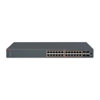
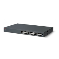
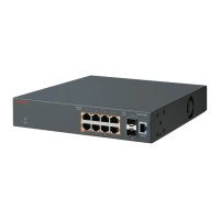
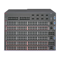
Figure 5: Redundant cascade stacking
1.
Base Unit
2. Last Unit
3. Cascade/Stack Cable
4. Cascade/stack Cable (Return cable to make stack resilient. Use longer stack cable
if required.)
In the example, the following occur:
• Unit 3 becomes nonoperational due to a unit failure, cable disconnection, or a loss of
power.
• Units 2 and 4, directly upstream and downstream from Unit 3, sense the loss of link signals
from unit 3. The software directs all the data to traverse the remaining path.
• The Cascade Down LED for Unit 2 and the Cascade Up LED for Unit 4 turn amber to
indicate an error.
• The remaining stack units remain connected and continue to operate.
Avaya Ethernet Routing Switch 3500 series stacking
February 2013 23

 Loading...


