Switch Model Key features Part Number
“C”: Includes power cord commonly used in the United Kingdom and Ireland.
“D”: Includes power cord commonly used in Japan.
“E”: Includes North American power cord.
“F”: Includes Australian power cord.
Depending on the switch model, a 250 W or 1025 W PSU and .5 m stacking cable is provided for all
switches.
Common hardware features
The following hardware features are part of all switches in ERS 4900 Series:
• Standard ERS 19 inch rack mount hole pattern allowing horizontal or vertical, flush or offset,
front or rear mount options
• Front panel:
- one serial console connection
- one USB 2.1 Type A port
- status LED display panel
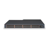
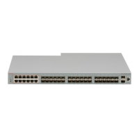
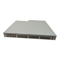
The following figure illustrates ERS 4900 Series front panel.
1. 10/100/1000 Ports (LEDs above the ports)
2. USB Type-A port
3. Reset push button
4. Status LEDs
5. SFP+ ports
6. Serial console port
Figure 1: Front panel
• Rear panel:
- two stack connectors
- one Base Select switch
- ports
Installing Ethernet Routing Switch 4900 Series
February 2016 Installing Avaya Ethernet Routing Switch 4900 Series 14
Comments on this document? infodev@avaya.com

 Loading...