Issue 2.1 June 2006 1227
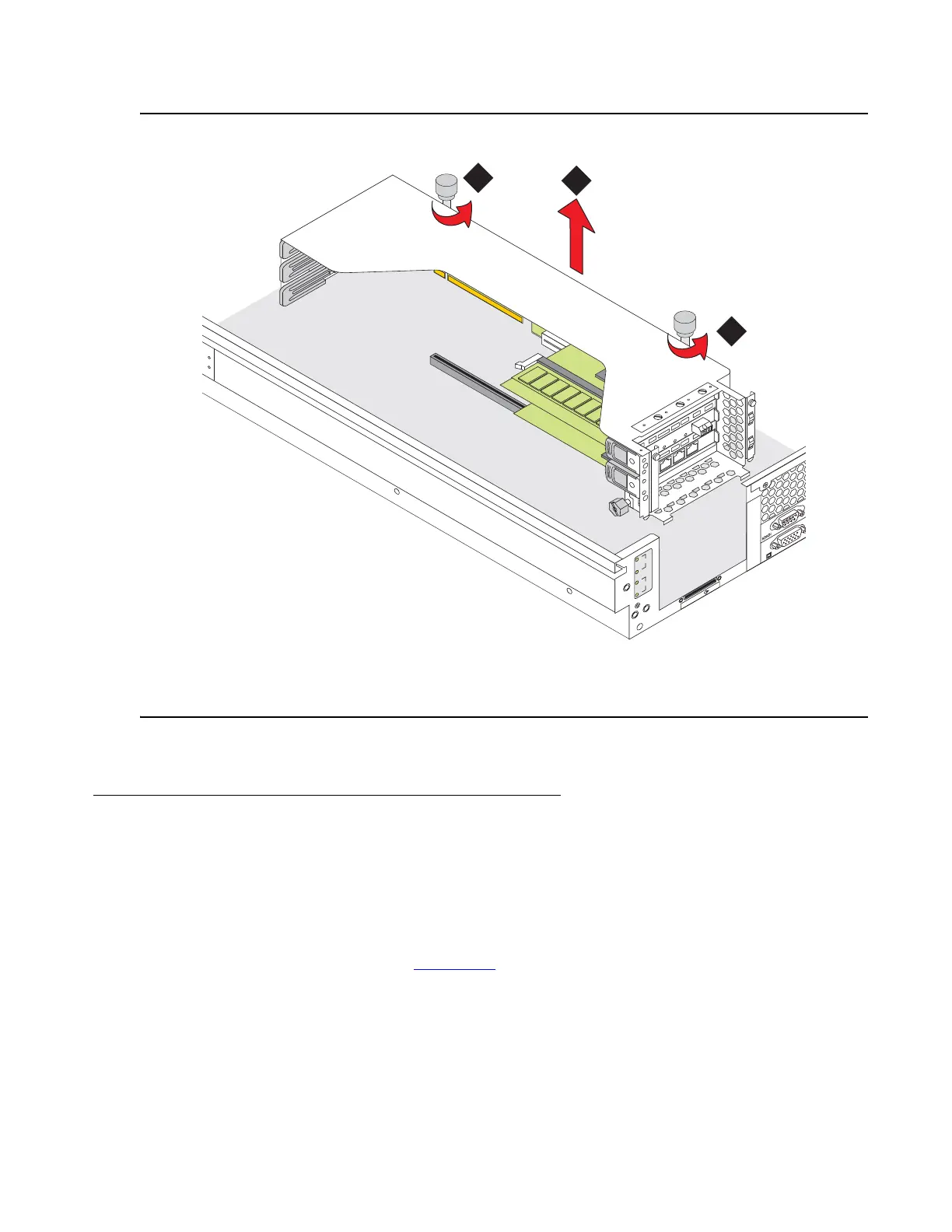
Figure 106: Remove the riser assembly
2. Lift the riser assembly straight up and set it on the antistatic mat.
Inserting the DAL1 circuit pack
To insert the DAL1 circuit pack:
1. Remove the DAL1 circuit pack from its protective packaging and set the circuit pack on the
antistatic mat beside the riser assembly.
2. Align the circuit pack with the riser assembly and push the circuit pack into the slot above
the quad-NIC circuit pack (see Figure 107
).
Figure notes:
1.
Loosen both thumbscrews.
2.
Lift riser assembly straight up.
2
3
VDCI
1
2
3
1
3
3
M
G
z
1
0
0
M
G
z
1
0
0
M
G
z
h3df87cr LAO 102505
DAL1
DUP
MEMORY
RECEIVE
MODE
LINC
SYNC
TRANS
MODE
LINC
ACTIVE
2
1
1

 Loading...