Important:
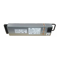
In addition to the fan modules, each power supply also has a fan. The power supply stops
working if a power supply fan fails, but there is no LED or software warning that indicates this
failure. Try to recover the power supply fan by resetting the switch. If the fan does not recover,
then replace the faulty power supply.
Table 9: Switch LED state indicators
Label Color and Status Description
PWR Off The switch is not receiving power and not operating.
Green (steady) The switch is receiving power from either one of the power
supplies (if two power supplies are installed).
Green (blinking) The switch is resetting.
Status Off The switch is non-operational.
Amber (steady) The switch encountered an error when running the diagnostic
software.
Amber (blinking) The switch is booting and running diagnostic software. This is
normal activity during the boot process.
Green (steady) The switch loaded the agent software code and is operating
normally.
Green (blinking) The switch is loading the agent software code.
RPS Off A second power supply is not present in either PSU1 or PSU2.
Amber (steady) The second power supply, which was operating in either PSU1
or PSU2, was removed from the chassis.
Amber (blinking) The second power supply in either PSU1 or PSU2 is present,
but not supplying power to the switch.
Green (steady) The second power supply (in either PSU1 or PSU2) is present
and operating normally as a redundant power supply (RPS).
Fan Amber (steady) A fan module has been removed.
Amber (blinking) A fan module has failed.
Green (steady) All fan modules are operating normally.
100 Mbps/1 Gbps/10 Gbps RJ-45 port LED state indicators
This section describes the RJ-45 copper port LED state indicators by color and fluctuation cues. The
up arrow on the left indicates the top port; the down arrow on the right indicates the bottom port.
LED state definitions
October 2015 Installing the Avaya VSP 7200 Series 37
Comments on this document? infodev@avaya.com

 Loading...


