Model 6700 Family User’s Manual
23
Error Codes
The 9-pin version of the 6700 has DE type
female connector accessible at the rear of the
unit. The functional pinout of this connector is
compatible with a standard PC with a pass-
through cable.
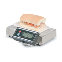
DE-9 Female Scale DE-9 Male Host
Pin Name Direction Pin Name Direction
1. JMP 1 - 1. DCD IN
2. TXD OUT 2. RXD IN
3. RXD IN 3. TXD OUT
4. JMP 1 - 4. DTR OUT
5. SG - 5. GRD -
6. JMP 1 - 6. DSR IN
7. JMP 2 - 7. RTS OUT
8. JMP 2 - 8. CTS IN
9. NC - 9. RI IN
Any system errors detected by the scale will be
displayed as the letter E followed by a two-digit
error code. Press the TEST key to continue
operation. If a calibration error occurs, the only
way to clear it is by recalibrating the scale.
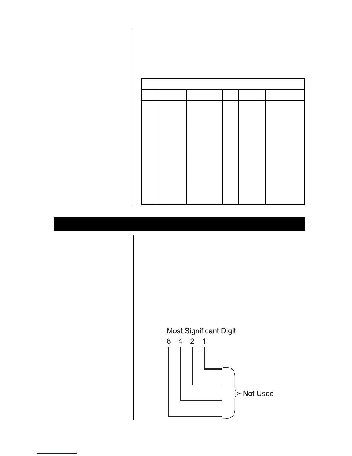
The error codes are broken down into two
hexadecimal numbers, with each bit defining a
single error condition. The error codes are
defined as follows:
RS-232 Interface
* Jmp1 and Jmp2 pins
are connected
internally on the scale
PCB connector.