XR Series Installation Instructions 19
4.1 Wiring the XR 4500, 4500TL or 6500
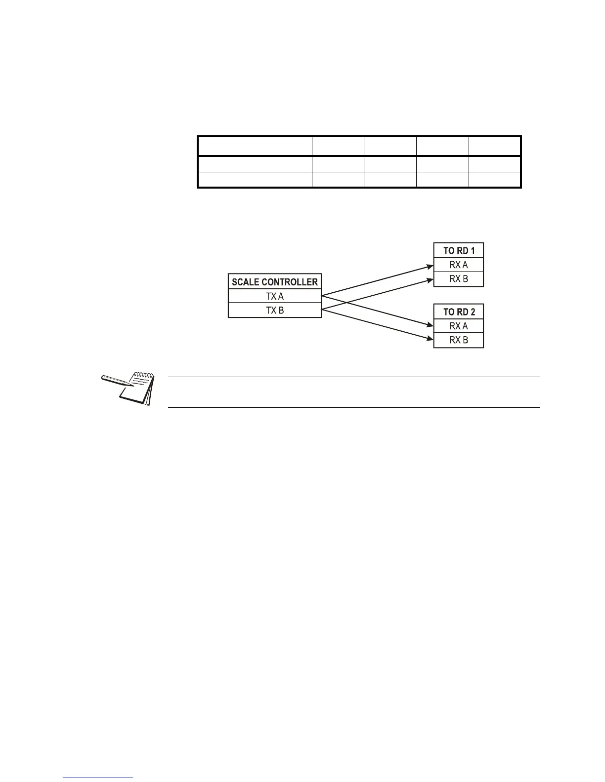
RS 485 Daisy Chain / Multi-Drop Wiring
Terminate the indicator’s communication wires at the RS 485 terminal (J4), shown in
Figure 4.1, using one of the following methods:
Parallel Multi-drop wiring
Split Multi-Drop Wiring
SCALE CONTROLLER TO RD 1 TO RD 2 TO RD 3 ETC.
TX A RX ARX ARX ARX A
TX B RX BRX BRX BRX B
Multi-Drop IDs are set using the Configuration Mode. For instructions see Parameter
1.4: Multi-Drop ID on page 32.
 Loading...