WEAT C2N – V1 - EN 9
Preliminary checks:
Before installing the motor, make sure:
The gate slides smoothly (rollers properly lubricated),
The gate is fitted with mechanical stops (opening and closing).
Installing the motor:
Unless otherwise indicated, all measurements are given in millimetres.
• After pouring a concrete pad and allowing it to cure, insert anchor bolts into the pad and fasten the base.
The base should be clean and level. Maintain the axis between the edge of the plate and the rack B.
Route the cable conduits through the holes A in the plate (see Figure 1).
• Fasten the motor to the base using the four screws supplied C. Adjust the motor horizontally by sliding it
into the slots in the anchor lugs D (Fig. 2).
• If the motor is fastened to an irregular surface, adjust the motor vertically. To do so, use grub screws and
three nuts on each screw, as illustrated in Figure 3. Adjust the nuts E and F until the motor is vertical.
• Adjust the motor so that it is horizontal both depthwise and widthwise.
• Fastening the rack: loosen the motor, slide the gate over and fasten the rack along its entire length. A
clearance of 2 or 3 mm must separate the pinion and the rack from one end of the rack to the other
(Fig. 4).
• Adjusting the stops: fasten the stops G on the rack (Fig. 5) so that the gate will stop approx. 20 mm
before the end stops, which must be fitted. To do so, use a 3 mm bit to drill two holes into the rack. Use
the stop as a jig. Fold the front of the stops slightly to make it easier to guide the switch onto the stops.
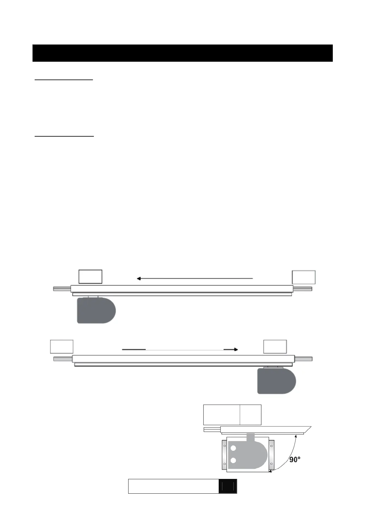
To prevent premature wear, fit the drive unit so that
the pinion moves at a 90° angle (see illustration
o
osite
.
8. INSTALLATION
Direction of o
enin
Direction of opening