3
CHAPTER
2
Hardware Installation and
Network Configuration
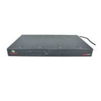
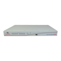
ESP-4 MI Hub Kit Contents
• ESP-4 MI serial hub.
• External power supply (PS) with attached PS-to-unit barrel connector. The line cord for the
power supply is appropriate to the intended country of operation.
• SuperSerial CD-ROM.
Modular adaptors are available from Avocent that allow a serial CAT 5 straight-through cable to
mate with the connector on the TD. See Adaptors on page 6.
Modular adaptors are also available for the modem emulation connection method. Contact Avocent
Technical Support for details.
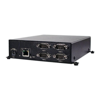
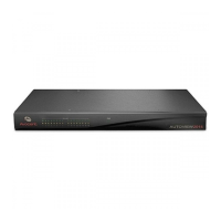
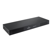
Hardware Overview
All connectors, LEDs and buttons are on the front of the ESP-4 MI serial hub.
The lower left corner of the front panel contains the electrical connector. For more information, see
Electrical on page 8.
The Ethernet port supports 10/100 auto detect (speed and duplex) connections. The LAN connector
accepts 10BaseT or 100BaseT LAN interface cable. A CAT 5 cable is required for 100BaseT
operation. Table 2.6 on page 7 lists the pin assignments. See Network interface on page 4 for
information about configuring the network interface.
The PORT 1, 2, 3 and 4 connectors are standard DB-9 DTE ports in RS-232 mode. Table 2.2 on
page 5 lists the pin assignments for each interface. The unit ships with RS-422 mode enabled for
all ports.
Table 2.1 describes the LEDs and buttons on the front panel.
Table 2.1: LEDs and Buttons
Item Description
POWER The POWER LED is lit when the hub is connected to a power source.
ON LINE
The ON LINE LED is lit (not blinking) when the hub’s self-test and initialization procedures
have completed successfully.