Chapter 2: Hardware Installation and Network Configuration 7
Table 2.5 lists the pin assignments for the RS-485 CAT 5 adaptor.
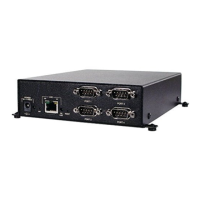
Ethernet connector
Table 2.6 lists the pin assignments for the RJ-45 shielded Ethernet connector.
Table 2.5: RS-485 CAT 5 Adaptor Pin Assignments
Pin Number - DB-9 RS-422 Description Pin Number - RJ-45
1 RxD (+) Receive Data (pos) 4
2 RxD (-) Receive Data (neg) 5
3 TxD (+) Transmit Data (pos) 4
4 TxD (-) Transmit Data (neg) 5
5 GND Ground N/C
6 DSR (RS-232) Data Set Ready N/C
7 RTS (RS-232) * Request to Send N/C
8 CTS (RS-232) * Clear to Send N/C
9 N/C N/A N/C
RxD(+) and TxD(+) are both connected to pin 4 of the RJ-45 connector.
RxD(-) and TxD(-) are both connected to pin 5 of the RJ-45 connector.
* RTS is tied to CTS inside the adaptor to indicate an RS-485 connection.
Table 2.6: Ethernet Connector Pin Assignments
Pin Signal
1 Transmit Data +
2 Transmit Data -
3 Receive Data +
4*
5*
6 Receive Data -
7*
8*
* These pins are usually connected in a standard Ethernet CAT 5 cable. There is special termination for these
signals in the interface to eliminate any problems if they are connected.