Chapter 2: Hardware Installation and Network Configuration 5
100 Mb/second, full duplex
100 Mb/second, half duplex
10 Mb/second, full duplex
10 Mb/second, half duplex
Pin Assignments
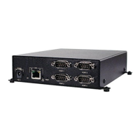
This section lists the pin assignments for the serial ports, available adaptors and the ESP-4 MI
serial hub Ethernet connector.
Serial ports
Table 2.2 lists the pin assignments for the RS-232 interface. This information is also provided on a
label on the bottom of the hub.
Table 2.3 lists the pin assignments for the RS-422 and RS-485 interfaces.
Table 2.2: RS-232 Serial Port Pin Assignments
Pin Number RS-232 Description Direction
1 DCD Data Carrier Detect Input
2 RxD Receive Data Input
3 TxD Transmit Data Output
4 DTR Data Terminal Ready Output
5 GND Ground N/A
6 DSR Data Set Ready Input
7 RTS Request to Send Output
8 CTS Clear to Send Input
9 N/C N/C N/A
Not supported: RI, RS-422 RTS and CTS differential control signals.
Unused pins (labeled N/C) should not have wires attached to them. Floating wires could cause unbalanced
noise, shorten overall distances and degrade performance.
Table 2.3: RS-422 and RS-485 Serial Port Pin Assignments
Pin Number RS-422/485 * Description Direction
1 RxD (+) Receive Data (pos) Input
2 RxD (-) Receive Data (neg) Input
3 TxD (+) Transmit Data (pos) Output