2017-10-03 | Technical improvements, changes in design, printing- and other errors expected. 5
2.
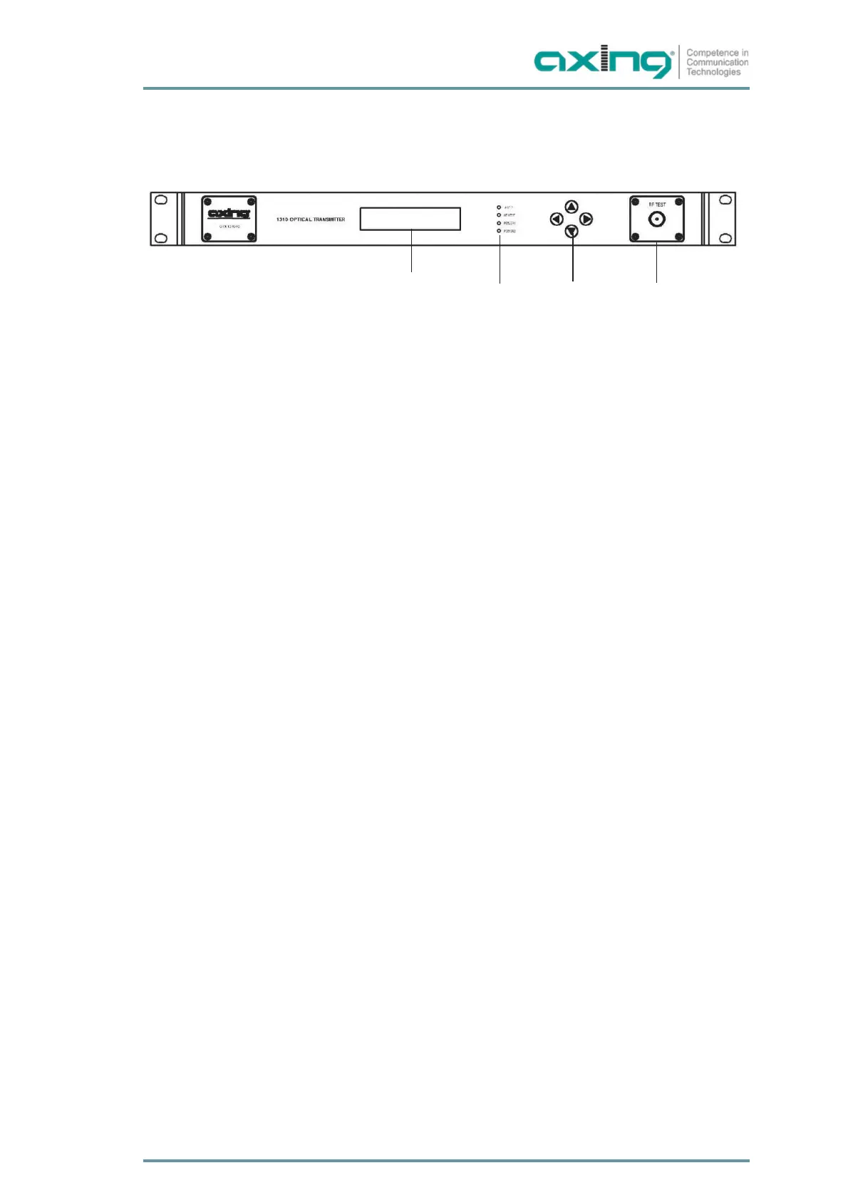
Front and rear panel
2.1.
Operating elements on the front panel
1
2 3 4
1. LCD Display
∂ Output power P(mW)
∂ Laser BIAS (mA)
∂ Laser Temperature T(℃)
∂ COOL CURRENT (mA)
∂ Power supply +24.4V, +5.4V, -5.4V’s Voltage detecting
∂ IP address
∂ Gateway
∂ OMI
∂ Inner temperature
2. LEDs (green means that it works fine, red means failed):
∂ RF is for input level status
∂ LASER is for laser working status
∂ PWR1 is for power supply one working status
∂ PWR2 is for power supply two working status
3. Back button, UP and DOWN Button, Enter button
4. RF TEST: Output with -20dBuV output level
 Loading...