AXISM1145-LNetworkCamera
Technicalspecifications
Buttons
ControlButton
Forlocationofthecontrolbutton,seeHardwareoverviewonpage7.
Thecontrolbuttonisusedfor:
•Resettingtheproducttofactorydefaultsettings.Seepage51.
•ConnectingtoanAXISVideoHostingSystemservice.Seepage43.Toconnect,pressandholdthebuttonforabout3
secondsuntiltheStatusLEDashesgreen.
•ConnectingtoAXISInternetDynamicDNSService.Seepage43.Toconnect,pressandholdthebuttonforabout3seconds.
Connectors
Networkconnector
RJ45EthernetconnectorwithPoweroverEthernet(PoE).
NO NO
NO
TICE TICE
TICE
Duetolocalregulationsortheenvironmentalandelectricalconditionsinwhichtheproductistobeused,ashieldednetwork
cable(STP)maybeappropriateorrequired.Allcablesconnectingtheproducttothenetworkandthatareroutedoutdoors
orindemandingelectricalenvironmentsshallbeintendedfortheirspecicuse.Makesurethatthenetworkdevicesare
installedinaccordancewiththemanufacturer’sinstructions.Forinformationaboutregulatoryrequirements,seethe
InstallationGuideavailableatwww.axis.com
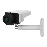
AboutI/Oconnectors
UsetheI/Oconnectorwithexternaldevicesincombinationwith,forexample,tamperingalarms,motiondetection,eventtriggering,
andalarmnotications.Inadditiontothe0VDCreferencepointandpower(DCoutput),theI/Oconnectorprovidestheinterfaceto:
Digitaloutput-ForconnectingexternaldevicessuchasrelaysandLEDs.ConnecteddevicescanbeactivatedbytheVAPIX®
ApplicationProgrammingInterfaceorintheproduct’swebpage.
Digitalinput-Forconnectingdevicesthatcantogglebetweenanopenandclosedcircuit,forexamplePIRsensors,door/window
contacts,andglassbreakdetectors.
4-pinterminalblock
FunctionPinNotes
Specications
0VDC(-)
1
0VDC
DCoutput
2
Canbeusedtopowerauxiliaryequipment.
Note:Thispincanonlybeusedaspowerout.
3.3VDC
Maxload=50mA
Digitalinput
3
Connecttopin1toactivate,orleaveoating(unconnected)
todeactivate
0tomax40VDC
Digitaloutput
4
Connectedtopin1whenactivated,oating(unconnected)
whendeactivated.Ifusedwithaninductiveload,e.g.arelay,
adiodemustbeconnectedinparallelwiththeload,for
protectionagainstvoltagetransients.
0tomax40VDC,opendrain,
100mA
57