1.
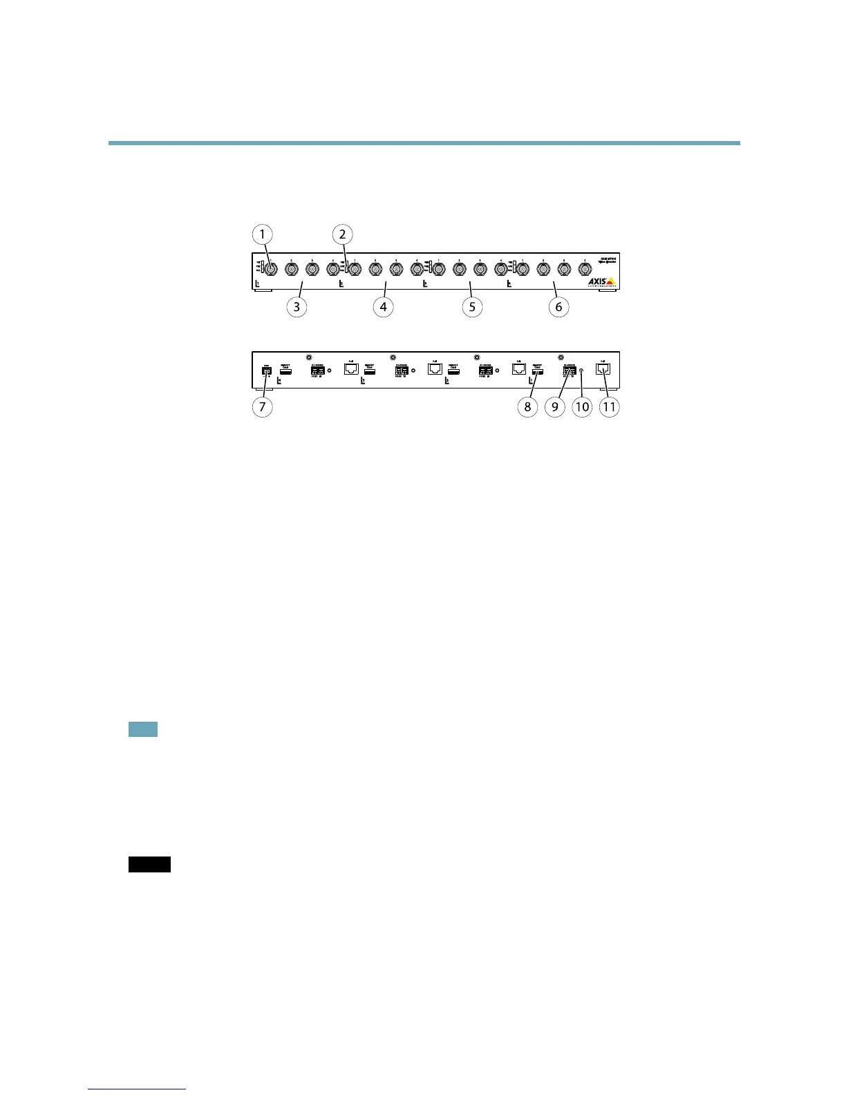
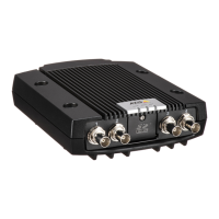
Videoinputconnectors
2.
LEDindicators
3.
Group1(4videoinputconnectors)
4.
Group2
5.
Group3
6.
Group4
7.
Powerconnector
8.
SDmemorycardslot(microSD)
9.
RS-485/RS-422connector
10.
Controlbutton
11.
Networkconnector(P0E)
ConnectorsandButtons
Fortechnicalspecications,seepage49.
BNCConnector
Eachvideoinputisterminatedusingacoax/BNCconnector.Connecta75Ohmcoaxialvideocable;therecommendedmaximum
lengthis250m(800ft).
Note
75Ohmvideoterminationcanbeenabled/disabledforthevideoinputthroughtheproduct'swebpageatVideo>Camera
Settings>Videotermination.Thisterminationisenabledonfactorydefault.Incaseswheretheproductistobeconnected
inparallelwithotherequipment,foroptimumvideoquality,itisrecommendedthatterminationbeenabledforonlythelast
deviceinthevideosignalchain.
NetworkConnector
RJ45Ethernetconnector.SupportsPoweroverEthernet(PoE).
NOTICE NOTICE
NOTICE
Theproductshallbeconnectedusingashieldednetworkcable(STP).Allcablesconnectingtheproducttothenetworkswitch
shallbeshielded(STP)andintendedfortheirspecicuse.Makesurethatthenetworkswitchisproperlygrounded.For
informationaboutregulatoryrequirements,seeRegulatoryInformation,onpage2.
PowerConnector
2-pinterminalblockforpowerinput.UseaSafetyExtraLowVoltage(SELV)compliantlimitedpowersource(LPS)witheitherarated
outputpowerlimitedto≤100Woraratedoutputcurrentlimitedto≤5A.
5