AXIS P13-E Network Camera Series Installation Guide Page 25
ENGLISH
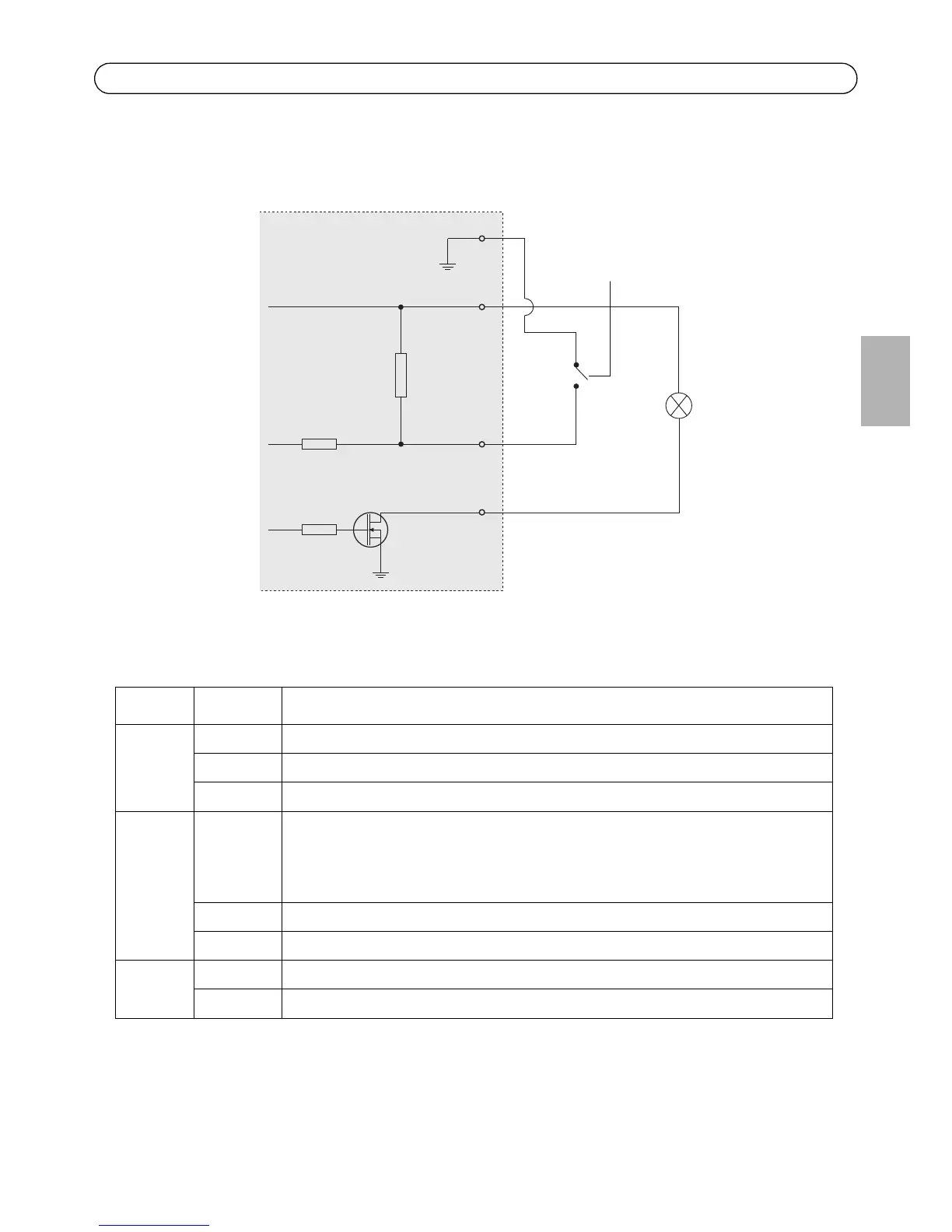
Connection diagram
The following connection diagram gives an example of how to connect an auxiliary device to the
network camera.
LED indicators
LED Color Indication
Network Green Steady for connection to a 100 Mbit/s network. Flashes for network activity.
Amber Steady for connection to 10 Mbit/s network. Flashes for network activity.
Unlit No network connection.
Status Green Steady green for normal operation.
Note: The Status LED can be configured to be unlit during normal operation, or to
flash only when the camera is accessed. To configure, go to Setup > System
Options > LED settings. See the online help files for more information.
Amber Steady during startup, during reset to factory default or when restoring settings.
Red Slow flash for failed upgrade.
Power Green Normal operation.
Amber Flashes green/amber during firmware upgrade.
1
2
E.g. push button
3
4
3.3V
max. 50mA
D
S
G