1
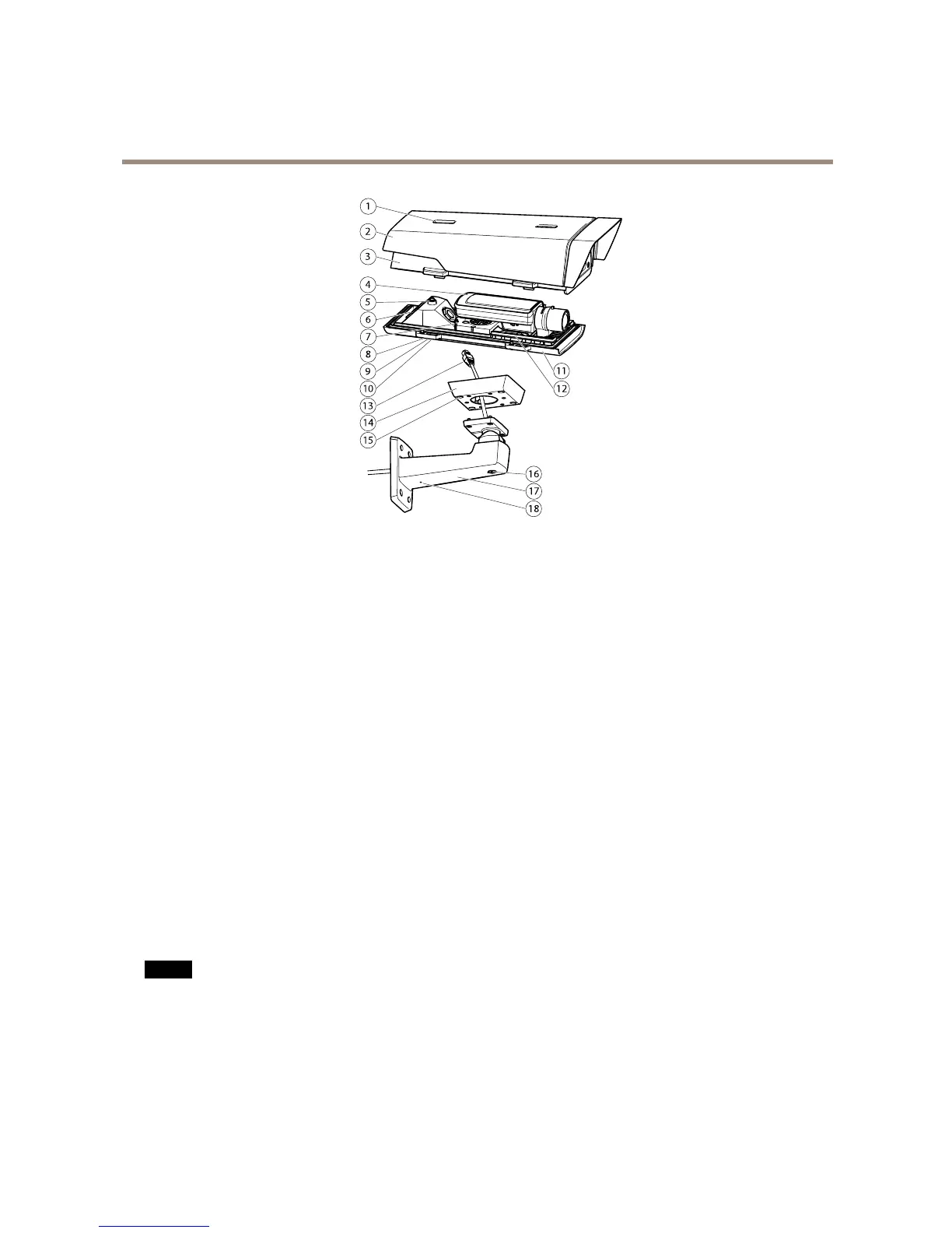
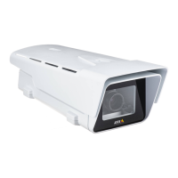
Sunshieldadjustment
2
Sunshield
3
Topcover
4
Networkcamera
5
Safetywiretab
6
Cablehole
7
Networkconnector
8
Bottomcoverscrews(4x)
9
Cablecover
10
Cablecoverscrews(2x)
11
Bottomcover
12
Heaters.Caution! Caution!
Caution!
Maybehot.
13
Networkcable(routethroughwallbracket)
14
Bracketadapter
15
Bracketscrews(4x)
16
Bracketadjustmentscrew
17
Wallbracket
18
Alternativecablehole
ConnectorsandButtons
Fortechnicalspecications,seepage66.
NetworkConnector
RJ45EthernetconnectorwithPoweroverEthernet(PoE).
NO NO
NO
TICE TICE
TICE
Theproductshallbeconnectedusingashieldednetworkcable(STP).Allcablesconnectingtheproducttothenetworkshall
beintendedfortheirspecicuse.Makesurethatthenetworkdevicesareinstalledinaccordancewiththemanufacturer’s
instructions.Forinformationaboutregulatoryrequirements,seeElectromagneticCompatibility(EMC)onpage2.
I/OConnector
Usewithexternaldevicesincombinationwith,forexample,tamperingalarms,motiondetection,eventtriggering,timelapserecording
andalarmnotications.Inadditiontothe0VDCreferencepointandpower(DCoutput),theI/Oconnectorprovidestheinterfaceto:
7