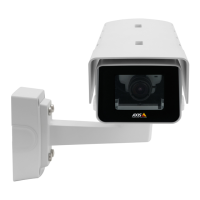
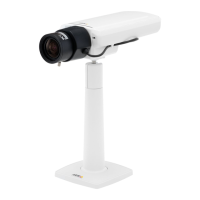
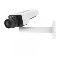
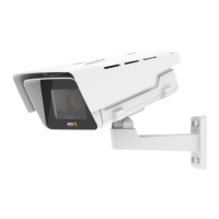
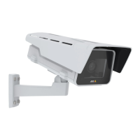
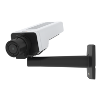
AXISP1365-ENetworkCamera
CableArea
NO NO
NO
TICE TICE
TICE
•Usecablesthatkeepwithinthespeciedcablearea.
•Selectcablesincompliancewithyourlocalregulations.
•Makesureallcableholesareproperlysealed.
Diameter
AWG
5–15mm(0.197–0.591in)
Approximately4–6/0
Tocreateextracableholes,openthedrill-outslocatedbelowtheholder.SeeHardwareOverview
onpage1
0.
NO NO
NO
TICE TICE
TICE
Usecablegasketsorcableglandsthatmatchboththecableholeandthecablearea.
Forinformationaboutaccessories,suchascablegasketsandcableglandsthatallowforother
cableareas,seewww.axis.com
InstalltheHardware
NO NO
NO
TICE TICE
TICE
•Duetolocalregulationsortheenvironmentalandelectricalconditionsinwhichthe
productistobeused,ashieldednetworkcable(STP)maybeappropriateorrequired.
Allcablesconnectingtheproducttothenetworkandthatareroutedoutdoorsorin
demandingelectricalenvironmentsshallbeintendedfortheirspecicuse.Makesurethat
thenetworkdevicesareinstalledinaccordancewiththemanufacturer’sinstructions.
Forinformationaboutregulatoryrequirements,seeRegulatoryInformation
•Becarefulnottoscratch,damageorleavengerprintsonthewindowbecausethiscould
decreaseimagequality.
TheAxisproductcanbeinstalledwiththecablesroutedthroughoralongthewall.
Readalltheinstructionsbeforeinstallingtheproduct:
1.Installthewallmount.SeeInstalltheWallMount.Fordetailedinstructions,seethewall
mount’sInstallationGuide,suppliedinthepackageoravailableonwww.axis.com
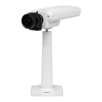
2.Attachthehousingtothewallmount.SeeAttachtheHousingtotheWallMount.
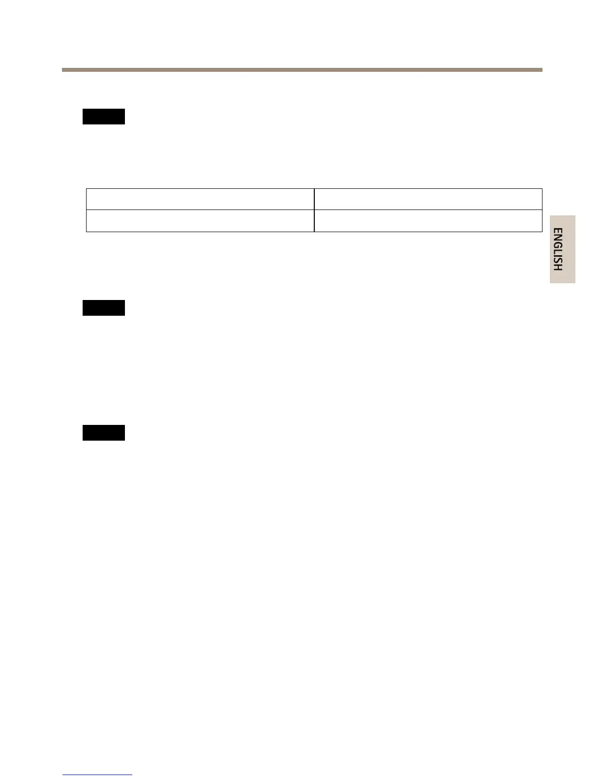
3.Installthecamerainthehousing.SeeInstalltheCameraintheHousing.
19