AXISQ1615-EMkIINetworkCamera
Connectors
I/Oconnector
4–pinterminalblock
Foranexamplediagram,seeConnectionDiagramsonpage17.
FunctionPinNotes
Specications
0VDC(-)
1
DCoutput
2
Canbeusedtopowerauxiliaryequipment.
Note:Thispincanonlybeusedaspowerout.
12VDC
Maxload=50mA
Digitalinput–Connecttopin1toactivate,
orleaveoating(unconnected)todeactivate.
0tomax30VDC Congurable
(Inputor
Output)
3–
4
Digitaloutput–Connectedtopin1when
activated,oating(unconnected)when
deactivated.Ifusedwithaninductiveload,
e.g.arelay,adiodemustbeconnectedin
parallelwiththeload,forprotectionagainst
voltagetransients.
0tomax30VDC,open
drain,100mA
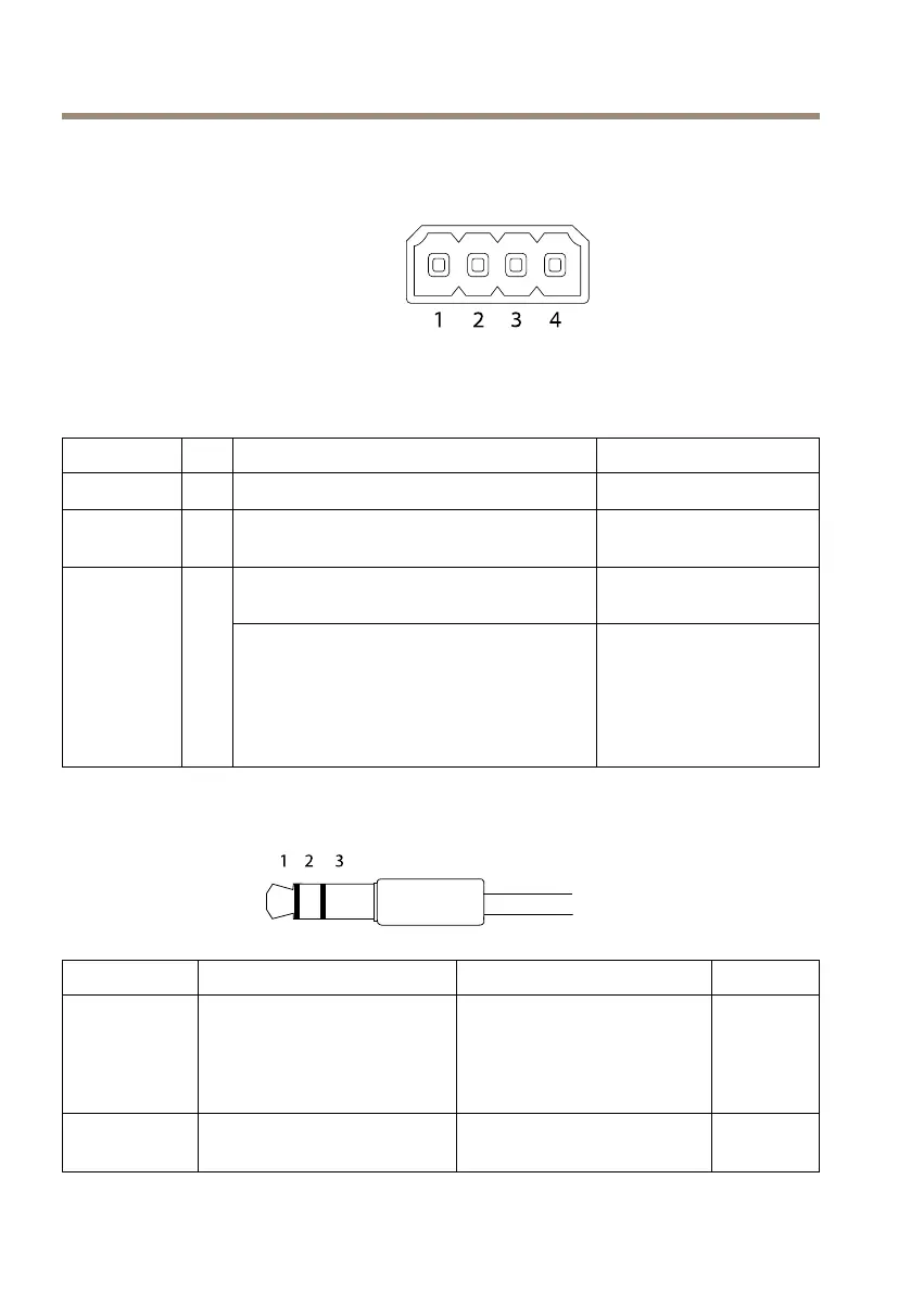
AudioConnector
3.5mmaudio
connectors(stereo)
1Tip2Ring
3Sleeve
AudioInputBalanced:‘Hot’signal
Microphone/Linein
Unbalanced:Microphone/Line
in
Balanced:‘Cold’signal
Microphone/Linein
Unbalanced:Unused
Ground
AudioOutput
Lineout,mono(stereo
connectorcompatible)
Lineout,mono(stereo
connectorcompatible)
Ground
18

 Loading...