9
AXIS Q19 Series - Product overview
Control button - The control button is used for
• Restoring the camera to factory default settings, see Resetting to the factory default settings, on page 49.
• Connecting to AXIS Internet Dynamic
DNS Service, see page 42. To connect, press the button once.
• Connecting to an AXIS Video Hosting System service, see page 42. To connect, press and hold the button until the sta-
tus LED flashes green.
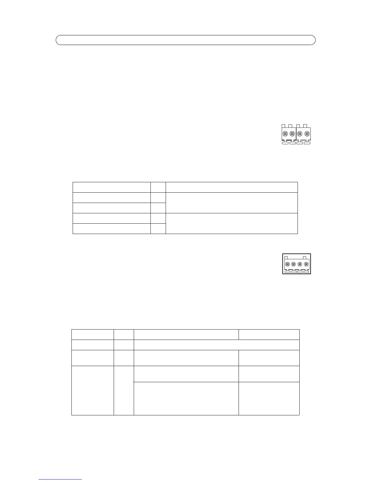
RS-485/422 connector - Two 2-pin terminal blocks for RS-485/422 serial interface used
to control auxiliary equipment, e.g.
PT devices.
The RS-485/422 serial port can be configured in the following port modes:
• Bidirectional RS-485 half-duplex port for data transmission using two wires, one combined
RX/TX pair.
• Bidirectional RS-485 full-duplex port for data transmission usi
ng four wires, one RX pair and
one TX pair.
• Unidirectional RS-422 port for transmitting or receiving data using two wires, RX- or TX
pair.
• Bidirectional RS-422 full duplex port for data transmission (point-t
o-point) using four wires, one RX pair and one TX
pair
RS 485/422TX(A) 1 TX pair for RS-422 and 4-wire RS-485
RS 485/422TX(B) 2
RS-485A alt RS-485/422RX(A) 3 RX pair for all modes (combined RX/TX for 2-wire RS-485)
RS-485B alt RS-485/422RX(B) 4
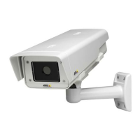
I/O terminal connector
Used in applications for e.g. motion detection, event triggering
and alarm notifications. In addition to an
auxiliary power and a GND pin, the network camera has 2 pins
that can be configured as either input or
output. These pins provide the interface to:
• Transistor output - For connecting external devices suc
h as relays and LEDs. Connected devices can
be activated by VAPIX application programming interface (API), by output buttons on the Live View page or by an
Event Type. The output will show as active (shown under Events > Port Status) if the alarm device is activated.
• Digital input - An alarm input for connecting devices that
can toggle between an open and closed circuit, for exam-
ple: PIRs, door/window contacts, glass break detectors, etc. When a signal
is received the state changes and the input
becomes active (shown under Events > Port Status.)
GND 1 Ground
3.3 V DC Power 2 Can be used to power auxiliary equipment.
Note: This pin can only be used as power out.
Max load = 250 mA
Configurable (Input
or Output)
3 - 4 Digital input - Connect to GND to activate, or leave
floa
ting (or unconnected) to deactivate.
0 to +40 V DC
Digital output — Internal connection to ground when
activated, float
ing (unconnected) when deactivated. If
used with an inductive load, e.g. a relay, a diode must
be connected in parallel with the load, for protection
against voltage transients
Max load = 100 mA
Max voltage = + 40 V DC
Function Pin Notes
Function Pin Notes Specifications