AXISQ9216-SLVNetworkCamera
Specifications
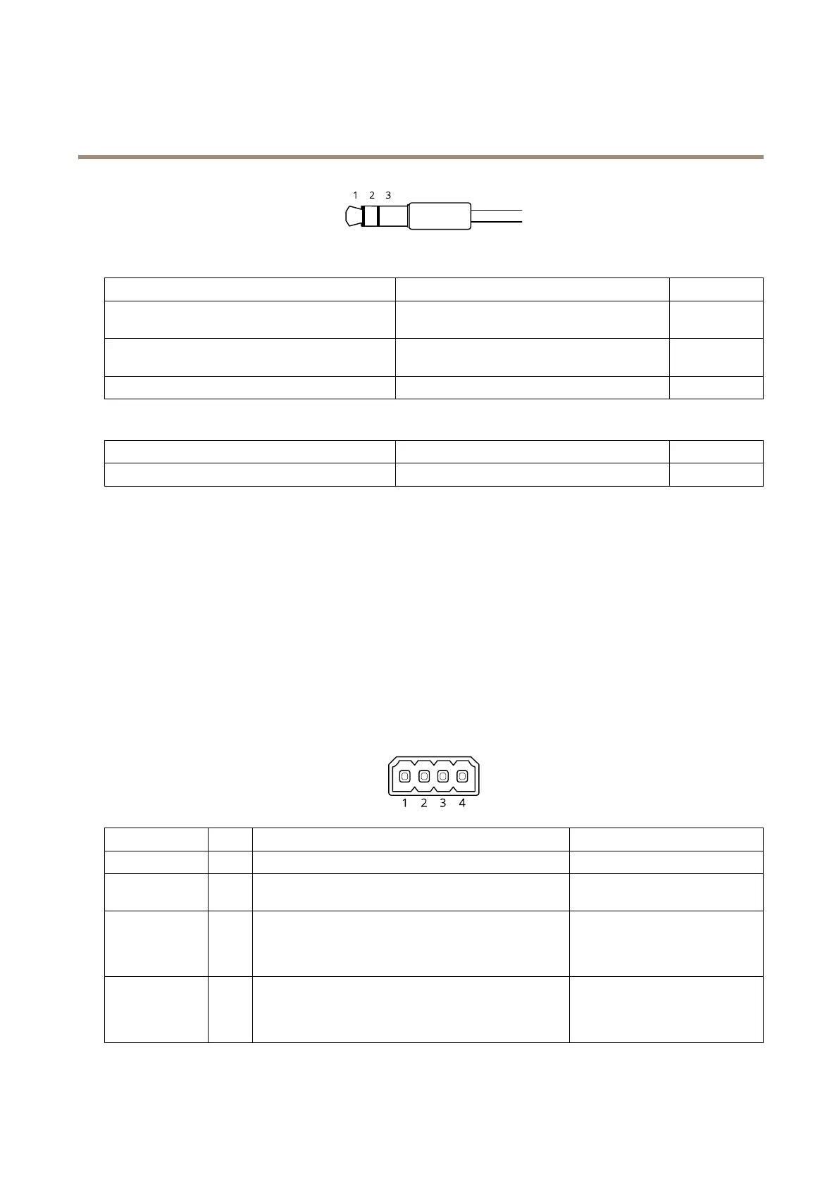
Audioinput
1Tip2Ring
3Sleeve
Unbalancedmicrophone(withorwithoutelectret
power)orline
Electretpowerifselected
Ground
Balancedmicrophone(withorwithoutphantompower)
orline,“hot”signal
Balancedmicrophone(withorwithoutphantom
power)orline,“cold”signal
Ground
DigitalsignalRingpowerifselected
Ground
Audiooutput
1Tip2Ring
3Sleeve
Balancedline,“hot”signalBalancedline,“cold”signal
Ground
Foraudioin,theleftchannelisusedfromastereosignal.
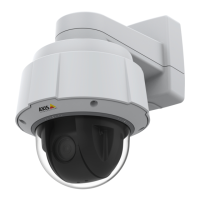
I/Oconnector
UsetheI/Oconnectorwithexternaldevicesincombinationwith,forexample,motiondetection,eventtriggering,andalarm
notications.Inadditiontothe0VDCreferencepointandpower(DCoutput),theI/Oconnectorprovidestheinterfaceto:
Digitalinput-Forconnectingdevicesthatcantogglebetweenanopenandclosedcircuit,forexamplePIRsensors,door/window
contacts,andglassbreakdetectors.
Supervisedinput-Enablespossibilitytodetecttamperingonadigitalinput.
Digitaloutput-ForconnectingexternaldevicessuchasrelaysandLEDs.ConnecteddevicescanbeactivatedbytheVAPIX®
ApplicationProgrammingInterface,troughaneventorfromtheproduct’swebpage.
4-pinterminalblock
FunctionPinNotes
Specications
DCground
1
0VDC
DCoutput
2
Canbeusedtopowerauxiliaryequipment.
Note:Thispincanonlybeusedaspowerout.
12VDC
Maxload=25mA
DigitalInputor
SupervisedInput
3
Connecttopin1toactivate,orleaveoating(unconnected)
todeactivate.Tousesupervisedinput,installend-of-line
resistors.Seeconnectiondiagramforinformationabouthow
toconnecttheresistors.
0tomax30VDC
DigitalOutput
4
Internallyconnectedtopin1(DCground)whenactive,
andoating(unconnected)wheninactive.Ifusedwithan
inductiveload,e.g.,arelay,connectadiodeinparallelwith
theload,toprotectagainstvoltagetransients.
0tomax30VDC,opendrain,
100mA
58