WHITE
AXMINSTER
W
10
Initial Assembly...
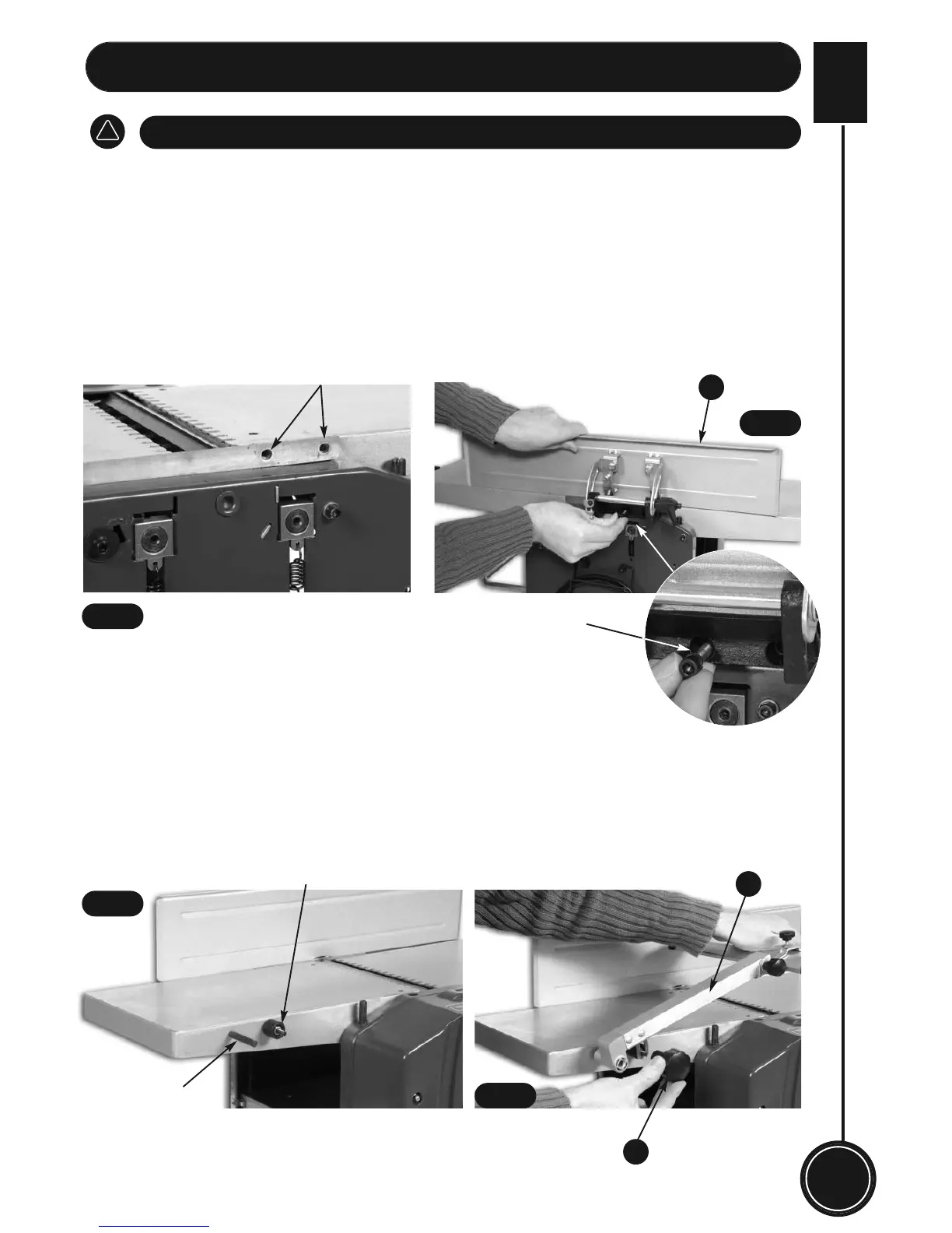
1. Fittting the Guide Fence
• Place the guide fence assembly (8) on the top of the right side plate. Be sure the two holes of
the guide fence assembly are aligned with the two pre-drilled holes in the table plate. (See Fig
1& 2)
• Secure the guide fence assembly (8) onto the planing table by using the two hex head screws
provided. (See Fig 1 & 2)
There is very little to do in the way of ‘initial assembly’. Just fit the guide fence and
cutter block mounting arm guard as described below:
DISCONNECT THE PLANER THICKNESSER FROM THE MAINS SUPPLY
!
8
3
2
Two pre-drilled holes
Hex head screw
Pin
Stem thread
Assembly Complete...
2. Fitting the Cutter Block Mounting Arm Guard
• Offer up the cutter block mounting arm guard (3) to the left side of the fixed infeed table. Line
up the two holes in the mounting arm (3) with the pin and thread stem in the fixed infeed table.
(See fig 3)
• Clamp the cutter block mounting arm guard in place with the mounting arm clamping knob (2).
(See fig 4)
Fig 1
Fig 2
Fig 3
Fig 4