37
MICROSPEED
REV 04/05
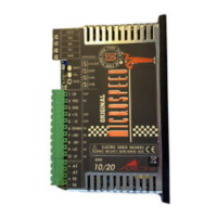
To insert the encoder board into the MICROSPEED,
follow these procedures:
-Take off the cover and remove the R screw.
-Insert the S stand-off in the R hole.
-Mount the encoder card (5.002.0) inserting the pin
strip into the Microspeed.
-Now,replace the R screw and affix the card.
If not specified,the Microspeed with encoder feedback
is supplied adjusted to 25Khz.
Encoder inputs Push-Pull ,Line-driver, Open-C.
Power supply levels From 0V to 5 min. 0V to 24V max.
Max. frequency 200 Khz
Encoder power supply S2 Close Vs=5V Max 75 mA
S2 Open Vs=12V Max.90 mA
Operating temperature0 - 40 C°
Code Description Pin out
+Vs Encoder power supply +5 /12V Output
GND GND Power supply Output
CHA Input channel A encoder Input
CHB Input channel B encoder Input
Code Description Standard
S1 Insert internal res. pull-up Open
S2 Select value Power supply Close
S3 Insert internal res. pull-up Open
Solder bridge description
Terminals description
Tecnical specification