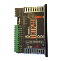
MICROSPEED
8
REV 04/05
J1 Normally open. If closed, the activation of IN
protection, inhibits the output of the drives OK transi-
stor. When this situation occurs the green OK LED is
OFF.
J2 -J4 Normally opens. (See chapter 6.5 Ramp time
adjustement).
J3 Normally closed. (See chapter 6.5 Ramp time
adjustement).
J5 -J6 Normally closed. If open, the dynamic constant
CKR and RKV must be inserted on the personalization
socket.(PI loop gain).
J7 Normally open. If closed, enable the armature
feedback (See chapter 6.6 )
Note:For the adjustements SC,SD,SE solder Bridges,
see page 40,42.
All of the adjustments are located in the area behind
the potentiometers .Its there that a socket containing
all of the adjustment components is located..
The socket is made by a double row of components
with pitch 7.62mm/0.3 (resistors) with 8+8 ways, and
2+2 ways for components with pitch 5.08 mm/0.2
(capacitors).
The resistors may be 1/4W.
(RDT)
(RA)
(RCA)
(RIN)
(RIP)
(RKV)
(GAIN)
(RAMP)
(pitch 5,08) (CKV)
(pitch 5,08) (CDER)
2.2 Solder bridges