41
MICROSPEED
REV 04/05
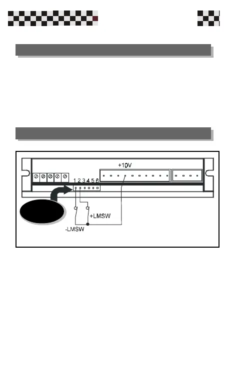
1 Input limit switch-
2 Input limit switch+
3 Test point tachogenerator signal (+/-8V)
4 Commond zero signal GND
5 Output current monitor (+/-7,5V=I pk)
6 N.C.
Function: At opening one of the following contacts you
disable the motor rotation in the corresponding direction.
The following figure shows an application with external
limit switch connections, using an internal power supply
+10V.
Input and output M3 connector (option)
Example of Limit Switch connection
M3(option)