18
Chapter 6. MAINTENANCE AND INSPECTION
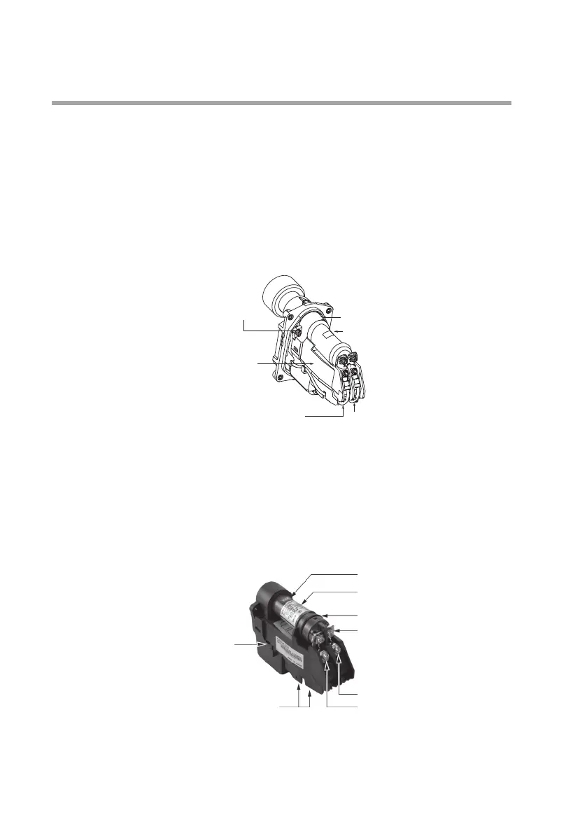
zRemoving of shutter unit and tube unit
(1) Turn off the power to the burner controller.
(2) After 1 min. has elapsed, remove 4 cover mounting screws to de-
tach the cover.
(3) Remove the 4 terminal screws to disconnect the lead wires (2
white, 1 blue, and 1 yellow) from the shutter unit.
(4) Remove the 2 shutter unit retaining screws.
(5) Dismantle by separating the flange unit and shutter unit at the top.
G terminal (yellow lead wire)
F terminal (blue lead wire)
Tube unit
Shutter unit
retaining screws (2)
O-ring
Shutter unit
(6) Remove the O-ring from the flange unit.
zMounting the shutter unit onto the flange unit
(1) Fit the O-ring that is included in the AUD Maintenance Kit onto
the flange unit.
(2) Loosen the 2screws holding the new (AUD Maintenance Kit)
tube unit and remove the tube unit, holding it by the back of the
unit.
Shutter unit
Terminal for shutter driver connection
(white lead wire)
Thermo label
Label
Tube unit
Tube unit retaining screw (2)
Terminal G (yellow lead wire)
Terminal F (blue lead wire)
 Loading...