16
Chapter 3. Operating This Device
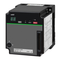
Part names
RESET switch
Switch to cancel a fault stop (Press for 1 second.)
Switch to clear an event (When there is no fault stop,
press and hold for 3 seconds.)
7-segment LED (green)
When normal: operating status code /
flame voltage / event code
When an error occurs: alarm code/ flame voltage
DISP switch
Switch to change display of flame voltage /
operating status code / event code / alarm code
Flame LED (green)
Lit when flame signal is detected.
Off when flame signal is off.
Front connector
Flame voltage output 0 to 5 V DC
Host communication (RS-485)
Loader jack
Smart Loader Package jack
Main unit mounting screw
Main unit mounting screw
Alarm LED (red)
ON when a fault stop occurs, OFF when there is
no fault stop.
While contact reset input is not accepted,
the alarm LED blinks.
The LED is ON when the flame detection circuit is
being checked.
All the LEDs are lit for 4 seconds after the power is turned on, and then they turn
off, and the display of the operating status code begins. If a fault stop occurs, the
alarm code and the code for the operating status where the fault stop occurred are
displayed alternately.
• Identifying information
Item Notation
Product number AUR355 _ _ _ _ _ _ _
Voltage AC _ _ _ V
Timing Flame failure response time FFRT _ s
z
7-segment display lower-right LED dot
If the dot at the bottom right of the 7-segment LED
is blinking, initialize the settings. For the method of
initialization, see Operation when the dot at the lower
right of the 7-segment LED is blinking (p.21).
Operation
z
DISP switch
z During normal operation
The 7-segment display shows the operating status code. Every time the DISP switch
is pressed, the display cycles through the operating status code, the flame voltage,
and (only if an event occurs) the event code.
• Operating status codes
Code Status
PF
Flame is being monitored.
PE
False flame is detected.
- -
Controlled shutdown

 Loading...