E2
STEP 1. MOUNTING
Location
Install the controller in a location that meets the following criteria:
•
Common mode voltages for I/O except power supply and relay contact
output: The voltage to ground is 30Vr.m.s. max., 42.4V peak max., and
60VDC max.
•
Neither high nor low temperature/humidity.
•
Free from silicone gas and other corrosive gases such as sulfide gas.
•
Little dust or soot.
•
Protected from direct sunlight, wind or rain.
•
Little mechanical vibration and shock.
•
Not close to a high voltage line, welding machine or other source of
electrical noise.
•
At least 15 meters away from a high voltage ignition device for a boiler.
•
No strong magnetic field.
•
No flammable liquid or gas.
•
Indoors
Mounting Procedure
•
The mounting must be horizontal within 10 degrees tilted in back side
lowering or within 10 degrees tilted in back side rising.
•
The mounting panel should be used with a thickness of less than 9mm
of firm board.
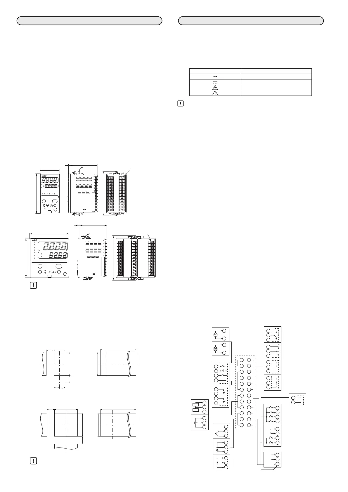
External Dimensions
z C35 (unit: mm)
para
enter
display
mode
pv
out
sp
ot2ot1ev3ev2ev1rspman
SDC35
48
Mounting
bracket
(Accessory)
108
Terminal
z C36 (unit: mm)
mode
display
enter
para
man
rsp
ev1
ev2
ev3
ot1
ot2
sp
out
pv
SDC36
96
Mounting bracket
(Accessory)
108
Handling Precautions
•
To fasten this controller onto the panel, tighten a mounting
bracket screws, and turn one more turn when there is no play
between the bracket and panel. Excessively tightening the
screws may deform the controller case.
•
Be sure to mount the unit in a panel so that operators do not
touch the rear terminal block.
Panel Cutout Dimensions
z C35 (unit: mm)
30
min.
92
44
30
min.
+0.5
0
+0.5
0
(48×N−4)
92
+0.5
0
+0.5
0
z C36 (unit: mm)
(96×N−4)
+0.5
0
92
+0.5
0
30
min.
92
30
min.
92
+0.5
0
+0.5
0
Handling Precautions
•
When three or more units are gang-mounted horizontally, the
maximum allowable ambient temperature is 40°C.
STEP 2. WIRING
All wiring should follow local regulations and be carried out by certified and
experienced personnel. Be sure to provide a switch within operator reach for
shutting OFF the main power supply to the controller in the main supply wir
-
ing. Also, in case of AC power supply models, the main supply wiring also
requires a time-lagged type (T) fuse (rated current: 0.5A, rated voltage: 250V).
(IEC127) The following table shows the meaning of the symbols in the termi
-
nal wiring label on the controller side:
Symbols Meaning
AC power supply
DC power supply
Caution, there is danger of electric shock
Caution
Handling Precautions
•
Before wiring the SDC35/36, verify the controller’s model No. and ter-
minal Nos. written on the label on the side of the body. Inspect all
wiring once wiring work for the SCD35/36 has been completed.
•
Use M3 crimp-type terminal lugs for wiring to terminal.
•
Leave at least 50 cm between I/O signal wires and power wires.
Do not put them in the same electrical conduit or duct.
•
Be careful not to allow any crimp-type terminal lugs to touch adja-
cent terminals.
•
To connect 2 (max.) crimp terminals to the same terminal screw, bend
the crimp terminals beforehand.
•
Prepare a heater current conductor to send a heater current through
the current transformer. Do not use a heater current that exceeds the
specified permissible current as this may damage the controller.
•
The current transformer input cannot be used for phase control.
•
If multiple current-input type SDCs are connected in series and you
want to turn them on/off individually, convert them to voltage input
by adding resistors (No. 81401325, sold separately) to the circuit.
•
There is no isolation provided between control output 1 and control
output 2. Install an isolator as required.
•
Do not connect a terminating resistor to either end of the RS-485
communications line. Doing so may interfere with communication.
•
If the motor connected to the motor drive relay output is used with
a 100/200VAC power supply, the use of an external auxiliary relay is
recommended. If an auxiliary relay is not used, thoroughly check the
operating conditions (operating voltage of the motor, inrush current,
frequency of switching, etc.) before use.
•
Do not wire in the same duct for the motor drive terminals (13), (14),
(15) and the MFB input terminals (7), (8), (9) and also do not use 6-core
cable. Failure to follow the instruction might cause controller mal-
function due to noise during motor startup operation.
•
Make sure that devices and equipment connected to this device have
reinforced insulation suitable for the maximum operating voltage of
this device’s power supply and input/output ports.
•
The controller requires maximum 5 seconds to start up once the
power is turned ON. The controller can be used once it has started up.
However, it is recommended to allow a warm-up time of at least 30
minutes to attain the specified accuracy.
13
14
15
13
14
+
−
13
14
15
1
2
+
−
+
16
17
+
−
22
23
24
DA
DB
SG
1
2
3
4
5
6
7
8
9
10
11
12
13
14
15
16
17
18
19
20
21
22
23
24
18
19
20
21
−
+
13
14
15
OPEN
CLOSE
NO
NC
1
2
1
2
3
4
5
6
3
4
5
6
2
1
2
3
1
COM
10
11
12
10
11
12
10
11
12
+
−
+
+
−
mA
V
C
B
A
mA/V
COM
COM
2DI
RSP
1
18
19
20
21
2
3
4
1
7
8
9
CT1
CT2
7
8
9
Y
T
G
Current
inputs
Auxiliary output
Communication
Digital input
Voltage
Voltage pulse/Current/Voltage
Current/Voltage/Voltage pulse
Voltage pulse /
Current / Voltage
Relay for
motor drive
Relay
RS-485
Event outputs
Relay
Relay
(independent contact)
MFB
RSP/DI
RSP input
Digital input
Power supply
AC power supply
100 to 240 V AC
DC power supply
24 V AC/24 V DC
(non polar)
Inputs
PV inputs
DC current
DC voltage
Thermocouple
RTD
DI
 Loading...


