E3
z I/O isolation
Items surrounded by solid lines are insulated from other signals.
Availability of input or output is based on a model number.
Power supply
Internal
Circuit
Control output 1
Control output 2
PV input
Current transformer input 1
Current transformer input 2
Motor feedback input
Loader communication
Auxiliary output
Digital input 1
Digital input 2
Digital input 3
Digital input 4
RS-485 communication
Event output 1*
Event output 2*
Event output 3
RSP input
* In case of independent contact, the part between the event
output 1 and the event output 2 is isolated.
SETTING THE PV RANGE TYPE
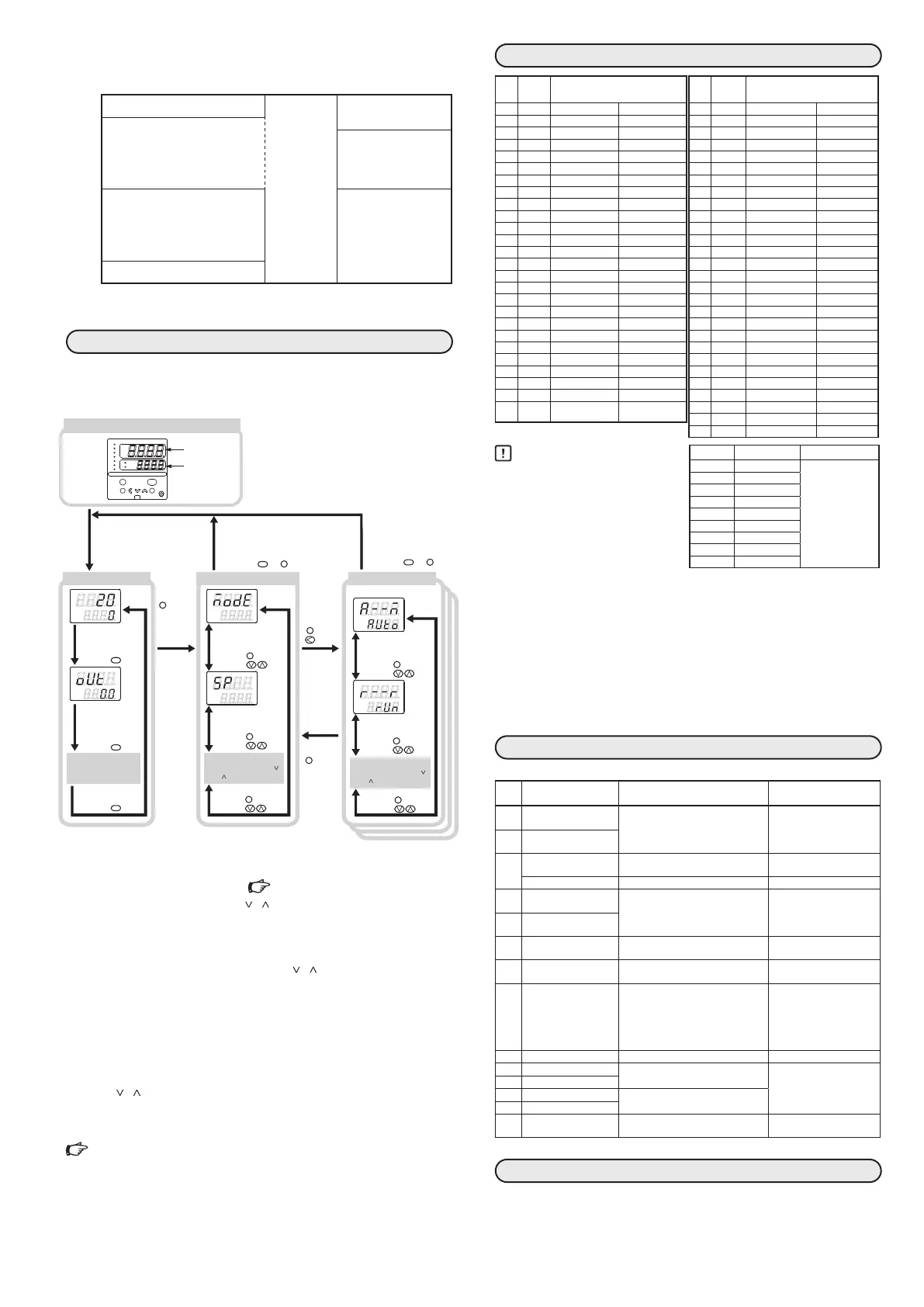
z Flowchart of key operations
There are the standard type and special type in the data setup
method. Here, the method is explained in the standard type.
Operation display Bank selection display Bank setup display
mode
display
enter
para
man
rsp
ev1
ev2
ev3
ot1
ot2
sp
out
pv
SDC36
The mode indicators are lit sequentially form
the left during a period of 5 to 6 sec after the
power has been turned ON while both the
upper display and lower display are OFF.
When all mode indicators have been lit, the
display is changed to the operation display.
(example. mode bank)
OFF
OFF
Display when the power is turned ON.
The display and setup status shown above are examples for explanation.
Therefore, some displays or settings are not shown actually according to
the model and/or setup contents.
No key operation for 3 minutes
or more.
mode
Press the or key.
display
No key operation for
3 minutes or more.
enter
Press the
or
key.
Keep the
key
pressed
for 2 sec.
or longer.
para
Mode bank selection
SP bank selection
Other display and setup
(Operate the [display]
key repeatedly.)
PV/SP display
display
key.Press the
display
key.Press the
display
key.Press the
MV display
para
key.Press the
key.Press the
para
key.Press the
key.Press the
para
key.Press the
key.Press the
para
key.Press the
key.Press the
Other banks
(Operate the [para], [ ]
and [ ] keys repeatedly.)
AUTO/MANUAL
change
RUN/READY change
para
key.Press the
key.Press the
para
key.Press the
key.Press the
Other setup
(Operate the [para], [ ]
and [ ] keys repeatedly.)
mode
Press the or key.
display
Keep the
key
pressed
for 2 sec.
or longer.
para
Step 3. Setting the PV range ( PV RANGE TABLE)
In the mode bank MOdE, press the [
] [ ] keys to display the setup bank
Stup, and then press the [enter] key.
>> C0 1 will be displayed on the upper display. Press the [enter] key again.
>> The lower display will be flashing.
Referring to the PV range table, press the [<] [
] [ ] keys to display the de-
sired sensor type for C0 1.
Press the [enter] key.
>> The flashing will stop and the settings will go into effect.
Step 4. Setting the SP
In the mode bank MOdE, press the [enter] key.
>> The lower display will be flashing.
Press the [
] [ ] keys to display the desired SP setting.
Press the [enter] key.
>> The flashing will stop and the settings will go into effect.
Single Loop Controller Model C35/36 User’s Manual for
Installation & Configuration CP-SP-1150E and Quick Reference
Guide for Model C35/36 CP-SP-1203E.
PV RANGE TABLE
C0
1
set
value
Input
type
Range
1 K −200 to +1200°C −300 to +2200°F
2 K 0 to 1200°C 0 to 2200°F
3 K 0.0 to 800.0°C 0 to 1500°F
4 K 0.0 to 600.0°C 0 to 1100°F
5 K 0.0 to 400.0°C 0 to 700°F
6 K −200.0 to +400.0°C −300 to +700°F
7 K −200.0 to +200.0°C −300 to +400°F
8 J 0 to 1200°C 0 to 2200°F
9 J 0.0 to 800.0°C 0 to 1500°F
10 J 0.0 to 600.0°C 0 to 1100°F
11 J −200.0 to +400.0°C −300 to +700°F
12 E 0.0 to 800.0°C 0 to 1500°F
13 E 0.0 to 600.0°C 0 to 1100°F
14 T −200.0 to +400.0°C −300 to +700°F
15 R 0 to 1600°C 0 to 3000°F
16 S 0 to 1600°C 0 to 3000°F
17 B 0 to 1800°C 0 to 3300°F
18 N 0 to 1300°C 0 to 2300°F
19 PLII 0 to 1300°C 0 to 2300°F
20 Wre5-26 0 to 1400°C 0 to 2400°F
21 Wre5-26 0 to 2300°C 0 to 4200°F
22 Ni-Ni·Mo 0 to 1300°C 0 to 2300°F
23 PR40-20 0 to 1900°C 0 to 3400°F
24 DIN U −200.0 to +400.0°C −300 to +700°F
25 DIN L −100.0 to +800.0°C −150 to +1500°F
26 Gold iron
chromel
0.0K to 360.0K 0 to 360K
C0
1
set
value
Input
type
Range
41 Pt100 −200.0 to +500.0°C −300 to +900°F
42 JPt100 −200.0 to +500.0°C −300 to +900°F
43 Pt100 −200.0 to +200.0°C −300 to +400°F
44 JPt100 −200.0 to +200.0°C −300 to +400°F
45 Pt100 −100.0 to +300.0°C −150 to +500°F
46 JPt100 −100.0 to +300.0°C −150 to +500°F
47 Pt100 −100.0 to +200.0°C −150 to +400°F
48 JPt100 −100.0 to +200.0°C −150 to +400°F
49 Pt100 −100.0 to +150.0°C −150 to +300°F
50 JPt100 −100.0 to +150.0°C −150 to +300°F
51 Pt100 −50.0 to +200.0°C −50 to +400°F
52 JPt100 −50.0 to +200.0°C −50 to +400°F
53 Pt100 −50.0 to +100.0°C −50 to +200°F
54 JPt100 −50.0 to +100.0°C −50 to +200°F
55 Pt100 −60.0 to +40.0°C −60 to +100°F
56 JPt100 −60.0 to +40.0°C −60 to +100°F
57 Pt100 −40.0 to +60.0°C −40 to +140°F
58 JPt100 −40.0 to +60.0°C −40 to +140°F
59 Pt100 −10.00 to +60.00°C −10 to +140°F
60 JPt100 −10.00 to +60.00°C −10 to +140°F
61 Pt100 0.0 to 100.0°C 0 to 200°F
62 JPt100 0.0 to 100.0°C 0 to 200°F
63 Pt100 0.0 to 200.0°C 0 to 400°F
64 JPt100 0.0 to 200.0°C 0 to 400°F
65 Pt100 0.0 to 300.0°C 0 to 500°F
66 JPt100 0.0 to 300.0°C 0 to 500°F
67 Pt100 0.0 to 500.0°C 0 to 900°F
68 JPt100 0.0 to 500.0°C 0 to 900°F
Handling Precautions
•
The accuracy varies according to
the range. The accuracy of the B
thermocouple is ±4.0%FS for a
range of 260°C or less, ±0.4%FS
for 260 to 800°C and ±0.2%FS for
800 to 1800°C.
The PV values under 20°C are not
shown. The accuracy of the No.15
(sensor type R) or No.16 (sensor type
S) is ±0.2%FS for a range of 100°C or less, and ±0.15%FS for 100 to 1600°C.
The accuracy of the No.23 (sensor type PR40-20) is ±2.5%FS for 0 to of
300°C, and ±1.5%FS for 300 to 800°C, ±0.5%FS for 800 to of 1900°C.
The accuracy of the No.26 (sensor type gold iron chromel) is ±1.5K.
The accuracy of the No. 55 to 62 and 81 are ±0.15%FS ±1digit for each
ranges. The accuracy of the No.19 (sensor type PLII) in the range of 0 to
32°F does not meet the indication accuracy.
•
The ranges with a decimal point show figures under decimal point.
•
Make sure to set the correct number in setup display C0 1, according to
the type and range of the sensor used. If the setting is wrong, problems
such as large temperature errors in the output may occur.
ALARM CODE TABLE
This table shows the alarm display and measures for the abnormal operation of this controller.
Alarm
code
Error Cause Corrective action
AL01
PV input failure
(over range)
Sensor line break, incorrect wiring,
incorrect PV range type setting
Checking wiring or reset PV
range type.
AL02
PV input failure
(under range)
AL03
CJ failure Terminal temperature is faulty
(thermocouple).
Checking the ambient
temperature.
PV input failure Sensor line break, incorrect wiring (RTD) Checking wiring.
AL05
RSP input failure *
1
(over range)
Sensor line break, incorrect wiring,
incorrect RSP range setting
Checking wiring or reset RSP
range code.
AL06
RSP input failure *
1
(under range)
AL07
MFB input failure Motor line break, incorrect wiring Checking wiring or conrm
the MFB input.
AL10
Motor adjustment failure Motor line break, incorrect wiring,
motor power supply failure.
Checking wiring, conrm the
motor power supply, reset.
AL11
CT input failure
(over-range)
(CT input 1 or 2, or both)
A current exceeding the upper limit of
the display range was measured. The
number of CT turns or the number of
CT power wire loops is incorrectly set,
or wiring is incorrect.
Use a CT with the correct
number of turns for the dis
-
play range, reset the number
of CT turns, reset the number
of CT power wire loops,
and/or check the wiring.
AL70
A/D conversion failure Defective A/D converter Replace unit.
AL95
Parameter failure Power turned OFF during xing data
Data corrupted due to noise, etc.
Re-start the system.
Reset data or replace unit.
(AL95/97: setting data,
AL96/98: tuning data)
AL96
Adjustment data
AL97
Parameter failure *
2
Data corrupted due to noise, etc.
AL98
Adjustment data failure *
2
AL99
ROM failure ROM (memory) error Re-start the system.
Replace unit.
*1. Displays in RSP mode *2. RAM area
MAINTENANCE
Cleaning:
When wiping out the SDC35/36, use the soft and dried cloth. Do not
use a detergent or an organic solvent like thinner or benzene.
Parts replacement: Do not replace the parts.
Fuse replacement: On AC models, when replacing the fuse for the power, make sure
that the replacement fuse complies with applicable standards. Use a
time lag fuse (T) compliant with IEC127 and rated at 250V, 0.5A.
C0
1
set value
Input type Range
81 0 to 10mV The scaling and
the decimal point
position can be
changed variably in
a range of −1999 to
+9999.
82 −10 to +10mV
83 0 to 100mV
84 0 to 1V
86 1 to 5V
87 0 to 5V
88 0 to 10V
89 0 to 20mA
90 4 to 20mA
 Loading...


