E4
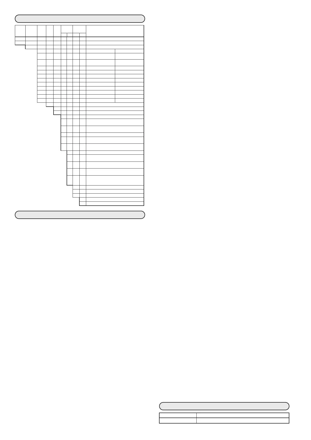
MODEL SELECTION TABLE
Basic
model
No.
Mounting Control
output
PV
input
Power
supply
Optional
functions
Additional
processing
Specifications
1 2 1 2
C35 48 × 96 size model
C36 96 × 96 size model
T Panel mounting type
Control output 1 Control output 2
R0 Relay contact output
N.O.
None (relay output for
control output 1: N.C.)
*1 R1
Relay contact output for
motor drive OPEN side
Relay contact output for
motor drive CLOSE side
V0 Voltage pulse output*
2
—
VC Voltage pulse output*
2
Current output
VD Voltage pulse output*
2
Voltage output
VV Voltage pulse output*
2
Voltage pulse output*
2
C0 Current output —
CC Current output Current output
CD Current output Voltage output
DO Voltage output —
DD Voltage output Voltage output
U Universal
A AC model (100 to 240VAC) 50/60Hz
D DC model (24VAC/24VDC)
1 Event relay output: 3 points
2 Event relay output 3 points,
Auxiliary output (current output)
3 Event relay output 3 points,
Auxiliary output (voltage output)
*1 4
Event output: 2 points (independent contact)
*1 5
Event output: 2 points (independent contact)
Auxiliary output (current output)
*1 6
Event output: 2 points (independent contact)
Auxiliary output (voltage output)
0
None
*3, *4 1 Current transformer input: 2 points
Digital input: 4 points
*3, *4 2
Current transformer input: 2 points
Digital input: 4 points, RS-485 communication
*3, *4 3 Current transformer input: 2 points
Digital input: 2 points, RSP input
*3, *4 4 Current transformer input: 2 points
Digital input: 2 points, RSP input, RS-485
communication
*1 Can not be selected for DC model.
*2 For SSR drive
*3 A current transformer is sold separately.
*4 When the control output is R1, the current
transformer input is not applied. MFB input
is applied.
0 No additional treatment
D Inspection certificate provided
Y
Complying with the traceability certification
0
None
A UL-marked product
SPECIFICATIONS
z PV input
Thermocouple:
K, J, E, T, R, S, B, N (JIS C1602-1995)
PL II (Engelhard Industries Data (ITS90))
WRe5-26 (ASTM E988-96(Reapproved 2002))
Ni-Ni·Mo (ASTM E1751-00)
PR40-20 (Johnson Matthey Data)
DIN U, DIN L (DIN 43710-1985)
Gold iron chromel (Hayashidenko Data)
Resistance temperature detector (RTD):
Pt100 (JIS C1604-1997), JPt100 (JIS C1604-1989)
DC voltage:
0 to 10mV, −10 to +10mV, 0 to 100mV,
0 to 1V, 1 to 5V, 0 to 5V, 0 to 10V
DC current:
0 to 20mA, 4 to 20mA
Sampling cycle:
100ms
Indication accuracy:
±0.1%FS±1digit, ±0.2%FS±1digit for a negative
area of the thermocouple (at ambient temperature
23±2°C)
Cold junction compensation accuracy:
±0.5
°C
(at ambient temperature 23±2°C)
±1.0
°C
(at ambient temperature 15 to 35°C)
±1.5
°C
(
at ambient temperature 0 to 15
°C
or 35 to 50°C)
Cold junction compensation method:
The compensation in the controller or the compen-
sation at the outside of the controller (0°C only)
can be selected.
Allowable input:
−0.5 to +12V (thermocouple, RTD, DC voltage)
30mA max or 4V max (DC current)
More than the allowable input voltage or current
may damage this device.
z Digital input
Number of inputs: 2 or 4 points
Input type:
Dry contact or open collector
Allowable ON contact resistance:
Max. 250Ω
Allowable OFF contact resistance:
Min. 100kΩ
Allowable ON residual voltage:
Max. 1.0V
Terminal current (ON):
Approx. 7.5mA (in case of short circuit).
Approx. 5.0mA
(in case of contact resistance 250Ω)
Minimum hold time:
200ms or more
z Current transformer input
Number of inputs:
2 points
Input object:
Current transformer with 100 to 4,000 turns
(availability is by 100-turn units)
Current measurement lower limit:
0.4A AC (800 turns, 1 time)
Formula; Number of turns ÷ (2000 × number of
power wire loops)
Current measurement upper limit:
50.0A AC (800 turns, 1 time)
Formula; Number of turns ÷ (16 × number of
power wire loops)
Allowable measured current:
70.0A AC (800 turns, 1 time)
Formula; Number of turns ÷ (16 × number of
power wire loops) × 1.4
Display range lower limit:
0.0A AC
Display range upper limit:
70.0A AC (800 turns, 1 time)
Formula; Number of turns ÷ (16 × number of
power wire loops) × 1.4
Display accuracy:
±5%FS
Display resolution:
0.1A AC
z Motor feedback potentiometer input (R1 model)
Allowable resistance:
100 to 2500Ω
Detection of line break:
Displays AL07.
z RSP input
Input type:
linear 0 to 20mA/4 to 20mA or linear 0 to 5V/1 to
5V/0 to 10V
Sampling cycle:
100ms
Indication accuracy:
±0.1%FS±1digit (at ambient temperature 23±2°C)
Operation at input break:
Downscale + AL06
z Control Output
• Relay output
Contact rating:
Control output 1: N.O. contacts,
250VAC/30VDC, 3A (resistive load)
Control output 2: N.C. contacts,
250VAC/30VDC, 1A (resistive load)
Life:
N.O. contacts, 50,000 cycles min.
N.C. contacts, 100,000 cycles min.
Min. switching specifications:
5V, 100mA
Min. open time/close times:
250ms
• Motor relay output (model R1)
Contact type:
1c (2 circuits: a contacts only)
Contact rating:
250VAC, 8A (resistive load)
250VAC, 2A (cos φ = 0.4)
24VDC, 2.5A (L/R = 0.7ms)
Life:
At least 120,000 cycles (at the rated resistive load)
At least 100,000 cycles (at the rated inductive load)
Minimum requirements for switching:
24VDC, 40mA
• Voltage pulse output (for SSR drive)
Open circuit voltage:
19VDC±15%
Internal resistance:
82Ω±0.5%
Allowable current:
Max. 24mA DC (a higher current might cause out-
put circuit failure)
Min OFF time/ON time:
1ms when the time proportional cycle time is less
than 10s.
250ms when the time proportional cycle time is
more than 10s.
• Current output
Output type:
0 to 20mA DC or 4 to 20mA DC
Allowable load resistance:
Max. 600Ω
Output accuracy:
±0.1%FS (at ambient temperature 23±2°C)
±1%FS at 0 to 1mA
• Voltage output
Output type:
0 to 5VDC/1 to 5VDC or 0 to 10VDC
Allowable load resistance:
Min. 1000Ω
Output accuracy:
±0.1%FS (at ambient temperature 23±2°C)
±1%FS at 0 to 0.05V
z Auxiliary output
• Current output
Output type:
0 to 20mA DC or 4 to 20mA DC
Allowable load resistance:
Max. 600Ω
Output accuracy:
±0.1%FS (at ambient temperature 23±2°C)
±1%FS at 0 to 1mA
• Voltage output
Output type:
0 to 5VDC/1 to 5VDC or 0 to 10VDC
Allowable load resistance:
Min. 1000Ω
Output accuracy:
±0.1%FS (at ambient temperature 23±2°C)
±1%FS at 0 to 0.05V
z Event relay outputs (ev1 to ev3)
Output rating:
250VAC/30VDC 2A (resistive load)
Life:
100,000 cycles min.
Min. switching specification:
5V, 10mA (reference value)
z RS-485 communication
Transmission line:
3-wire system
Transmission speed:
4800, 9600, 19200, 38400bps
Communication protocol:
CPL and Modbus conforming
Terminating resistor:
Do not connect a terminating resistor.
z Environmental condition
• Operating conditions
Ambient temperature:
0 to 50°C (Gang-mounting: 0 to 40°C)
Ambient humidity:
10 to 90%RH (non-condensing)
Rated power supply voltage:
AC model 100 to 240VAC, 50/60Hz
DC model 24VAC 50/60Hz, 24VDC
Power supply voltage range:
AC model 85 to 264VAC, 50/60±2Hz
DC model 21.6 to 26.4VAC 50/60±2Hz, 21.6 to 26.4VDC
• Transport conditions
Ambient temperature:
–20 to +70°C
Ambient humidity:
10 to 95%RH (non condensing)
z Other specifications
Power consumption:
Max. 12VA for AC model
Max. 12VA for DC model at 24VAC
Max. 8W for DC model at 24VDC
Non-detected power failure time:
Max. 20ms (AC model)
No power failure allowed (DC model)
Altitude:
2000m or less
Mass:
C35 Approx.250g (with mounting bracket)
C36 Approx.300g (with mounting bracket)
Terminal screw tightening torque:
0.4 to 0.6N·m
Applicable standards:
EN61010-1,
EN61326-1 (For use in industrial locations)
During EMC testing, the reading or output may
fluctuate by ±10%FS.
Overvoltage category:
Category II (IEC60364-4-443, IEC60664-1)
Allowable pollution degree:
Pollution degree 2
ACCESSORIES
Name Model No.
Mounting bracket 81409654-001 (Accessory)
 Loading...


