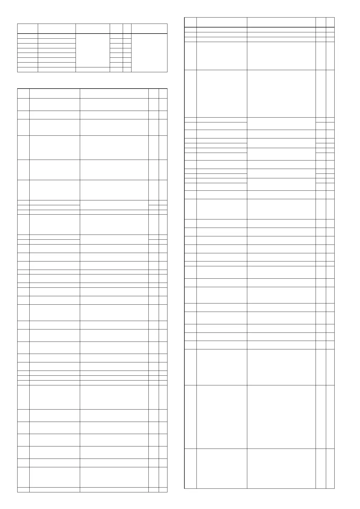
E6
Zone bank: ZOne
Display Item Contents Initial
value
User
level
Remarks
ZN- 1
Zone 1 –1999 to +9999U 9999U 2 Displayed when the
zone PID operation is
used (C24≠0).
ZN-2
Zone 2 9999U 2
ZN-3
Zone 3 9999U 2
ZN-4
Zone 4 9999U 2
ZN-5
Zone 5 9999U 2
ZN-6
Zone 6 9999U 2
ZN-7
Zone 7 9999U 2
ZN.df
Zone hysteresis 0 to 9999 5U 2
[List of Setup Setting Displays]
Setup bank: StUP
Display Item Contents Initial
value
User
level
C 0 1
PV input range type Thermocouple: 1 to 26
RTD: 41 to 68
DC current/voltage: 81 to 84, 86 to 90
88 0
C 02
Temperature unit 0: Centigrade (°C)
1: Fahrenheit (°F)
0 0
C 03
Cold junction compensation 0: Cold junction compensation is performed.
(Internal)
1: Cold junction compensation is not performed.
(External)
0 2
C 04
Decimal point position 0: No decimal point
1: One digit after decimal point
2: Two digits after decimal point
3: Three digits after decimal point
(Select “0” or“1” for the thermocouple/RTD
range with decimal point)
0 0
C 05
PV range low limit When the PV input range type is thermocouple
or RTD, the setting is disabled although range
low limit is displayed.
–1999 to +9999U when the PV input range type
is DC voltage/current.
0 0
C 06
PV range high limit When the PV input range type is thermocouple
or RTD, the setting is disabled although range
high limit is displayed.
–1999 to +9999U when the PV input range type
is DC voltage/current.
1000 0
C 07
SP low limit PV input range low limit to PV input range
high limit
0 1
C 08
SP high limit 1000 1
C 09
Square root extraction dropout 0.0 to 100.0% (0.0: No square root extraction) 0.0 2
C 10
RSP range type 0: 4 to 20mA
1: 0 to 20mA
2: 0 to 5V
3: 1 to 5V
4: 0 to 10V
0 0
C 1 1
RSP range low limit –1999 to +9999U 0 0
C 12
RSP range high limit 1000 0
C 13
PID calculation adjustment
function
0: Enabled
1: Disabled
0 2
C 14
Control action (direct/reverse) 0: Heat control (reverse action)
1: Cool control (direct action)
0 0
C 15
Selection of MV at PV alarm
occurrence
0: Control operation is continued.
1: MV at PV alarm occurrence is outputted.
0 2
C 16
MV at PV alarm occurrence –10.0 to +110.0% 0.0 2
C 17
MV at READY (at heat-side for heat/
cool control)
–10.0 to +110.0% 0.0 1
C 18
MV at READY (at cool-side) –10.0 to +110.0% 0.0 1
C 19
Operation at MANUAL change 0: Bump-less
1: Preset
0 1
C 20
Preset MANUAL value –10.0 to +110.0% (Used even at MANUAL mode
when power is ON.)
0.0 or
50.0
1
C 2 1
PID operation initialization
function selection
0: Automatic
1: Not initialized
2: Initialized (when SP value different from
current value is inputted.)
0 2
C 22
PID operation initial MV –10.0 to +110.0% 0.0 or
50.0
2
C 23
Control parameter decimal point 0: No decimal point
2: One digit after decimal point (Decimal point
of integration time or derivative time)
0 2
C 24
Zone PID action selection 0: Disabled
1: Selection by SP
2: Selection by PV
0 2
C 26
Heat/cool control selection 0: Disabled
1: Enabled
0 0
C 27
Heal/cool selection 0: Normal
1: Energy saving
0 1
C 28
Dead zone –100.0 to +100.0% 0.0 0
C 29
Heal/cool control selection point –10.0 to +110.0% 50.0 2
C 30
LSP setting system 1 to 8 1 0
C 3 1
SP ramp type 0: Standard
1: Multi-ramp
2: Step operation. Step is stopped when power
is re-supplied. (READY)
3: Step operation. Step is recovered when power
is re-supplied.
0 2
C 32
SP ramp unit 0: 0.1U/s
1: 0.1U/min
2: 0.1U/h
1 2
C 33
Step operation time unit 0: 0.1s
1: 1s (Displayed in min.s in console.)
2: 1min (Displayed in h.min in console.)
0 2
C 34
Step operation PV start 0: None
1: Up start
2: Down start
0 2
C 35
Step operation loop 0: Stop (Not looped.)
1: Looped.
2: Final step continued. (Not looped.)
0 2
C 36
CT1 operation type 0: Heater burnout detection
1: Current value measurement
0 0
C 37
CT1 output 0: Control output 1
1: Control output 2
2: Event output 1
3: Event output 2
4: Event output 3
0 0
C 38
CT1 measurement wait time 30 to 300ms 30 0
Display Item Contents Initial
value
User
level
C 39
CT2 operation type Same as CT1. 0 0
C 40
CT2 output Same as CT1. 0 0
C 4 1
CT2 measurement wait time Same as CT1. 30 0
C 42
Control output 1 range Current output:
1: 4 to 20mA
2: 0 to 20mA
Continuous voltage output:
1: 1 to 5V
2: 0 to 5V
3: 0 to 10V
1 0
C 43
Control output 1 type 0: MV
1: Heat MV (for heat/cool control)
2: Cool MV (for heat/cool control)
3: PV
4: PV before ratio bias filter
5: SP
6: Deviation (PV-SP)
7: CT1 current value
8: CT2 current value
9: MFB (Including estimation MFB)
10: SP+MV
11: PV+MV
0 0
C 44
Control output 1 scaling low limit –1999 to +9999 (The decimal point position
and unit may vary depending on the control
output 1 type.)
0.0 0
C 45
Control output 1 scaling high limit 100.0 0
C 46
Control output 1 MV scalable
bandwidth
0 to 9999 (Available when control output 1 type
is 10 or 11.)
200.0 0
C 47
Control output 2 range Same as control output 1. 1 0
C 48
Control output 2 type 3 0
C 49
Control output 2 scaling low limit –1999 to +9999 (The decimal point position
and unit may vary depending on the control
output 2 type.)
0 0
C 50
Control output 2 scaling high limit 1000 0
C 5 1
Control output 2 MV scalable
bandwidth
0 to 9999 (Available when control output 2 type
is 10 or 11.)
200.0 0
C 52
Auxiliary output range Same as control output 1 1 0
C 53
Auxiliary output type 3 0
C 54
Auxiliary output scaling low limit –1999 to +9999 (The decimal point position
and unit may vary depending on the auxiliary
output type.)
0 0
C 55
Auxiliary output scaling high limit 1000 0
C 56
Auxiliary output MV scalable
bandwidth
0 to 9999 (Available when auxiliary output type
is 10 or 11.)
200 0
C 57
Position proportional control
method selection
0: MFB control + estimated position control*
1: MFB control*
2: Estimated position control (MFB disabled)
3: Estimated position control (MFB disabled) +
position adjustment at power supply ON
0 0
C 58
Position proportional control
dead zone
0.5 to 25.0% 10.0 0
C 59
Position proportional control
long life
0: Controllability aiming type
1: Potentiometer life aiming type
1 0
C 60
Position proportional control
tuning
0: Stop
1: Start
0 0
C 6 1
Position proportional fullclose
tuning value
0 to 9999 1000 0
C 62
Position proportional fullopen
tuning value
0 to 9999 3000 0
C 63
Position proportional fullopen time 5.0 to 240.0s 30.0 0
C 64
Communication type 0: CPL
1: Modbus/ASCII format
2: Modbus/RTU format
0 0
C 65
Station address 0 to 127 (Communication is disabled when
“0” is set.)
0 0
C 66
Transmission speed 0: 4800bps
1: 9600bps
2: 19200bps
3: 38400bps
2 0
C 67
Data format (data length) 0: 7bit
1: 8bit
1 0
C 68
Data format (parity) 0: Even parity
1: Odd parity
2: No parity
0 0
C 69
Data format (stop bits) 0: 1bit
1: 2bits
0 0
C 70
Communication minimum
response time
1 to 250ms 3 2
C 7 1
Key operation type 0: Standard type
1: Special type
0 2
C 72
mode key function 0: Invalid
1: AUTO/MANUAL selection
2: RUN/READY selection
3: AT Stop/Start
4: LSP group selection
5: Release of all DO latches
6: LSP/RSP selection
7: Communication DI1 selection
8: Invalid
1 0
C 73
Mode display setup Whether the mode bank setup display is
enabled or disabled is determined by the sum of
the following weighting:
Bit 0: AUTO/MANUAL display
0: Disabled, +1: Enabled
Bit 1: RUN/READY display
0: Disabled, +2: Enabled
Bit 2: LSP/RSP display
0: Disabled, +4: Enabled
Bit 3: AT stop/start display
0: Disabled, +8: Enabled
Bit 4: DO latch release
0: Disabled, +16: Enabled
Bit 5: Communication DI1 ON/OFF display
0: Disabled, +32: Enabled
Other invalid setup: 0, +64, +128
255 1
C 74
PV/SP value display setup Whether the basic display is enabled or disabled
is determined by the sum of the following
weighting:
Bit 0: PV display
0: Disabled, +1: Enabled
Bit 1: SP display
0: Disabled, +2: Enabled
Bit 2: LSP group No. display
0: Disabled, +4: Enabled
Other invalid setup: 0, +8
15 1
* When C57 is set to “0” or “1”, set C60 to “1” and be sure to execute the position proportional control tuning.
 Loading...


