E8E8
1-12-2 Kawana, Fujisawa
Kanagawa 251-8522 Japan
URL
(11)
Specifications are subject to change without notice.
© 2003–2021 Azbil Corporation. All Rights Reserved.
1st edition: Sep. 2003
29th edition: July 2021 (M)
Display Item Contents Initial
value
User
level
dI 1.7 to
dI 5.7
Internal contact 1 to 5
Polarity A to D
Digits are called as 1st digit, 2nd digit, 3rd digit
and 4th digit from the right end digit.
0000 2
1st digit: Polarity A*
1
0: Direct
1: Reverse
0
2nd digit: Polarity B*
2
0
3rd digit: Polarity C*
3
0
4th digit: Polarity D*
4
0
dI 1.8 to
dI 5.8
Internal contact 1 to 5
Polarity
0: Direct
1: Reverse
0 2
dI 1.9 to
dI 5.9
Internal contact 1 to 5
Internal event
No. assignment
0: Every internal event
1 to 8: Internal event numbers
0 2
*1. Polarity of input assignment A *2. Polarity of input assignment B *3. Polarity of input assignment C
*4. Polarity of input assignment D
Do assignment bank: dO
Display Item Contents Initial
value
User
level
Ot 1. 1 to
Ot2. 1
Ev 1. 1
to
Ev3. 1
Control output 1 to 2,
event output 1 to 3
Operation type
0: Input of default
1: MV1 (ON/OFF control output, time
proportional output, heat-side proportional
output of heat/cool control)
2: MV2 (cool-side proportional output of heat/
cool control)
3: Function 1 ((A and B) or (C and D))
4: Function 2 ((A or B) and (C or D))
5: Function 3 (A or B or C or D)
6: Function 4 (A and B and C and D)
0 2
Ot 1.2 to
Ot2.2
Ev 1.2
to
Ev3.2
Control output 1 to 2,
event output 1 to 3
Output assignment A
0: Normally open (OFF, 0)
1: Normally close (ON, 1)
2: Internal event 1
3: Internal event 2
4: Internal event 3
5: Internal event 4
6: Internal event 5
7: Internal event 6
8: Internal event 7
9: Internal event 8
10 to 13: Undefined
14: MV1
15: MV2
16, 17: Undefined
18: DI1
19: DI2
20: DI3
21: DI4
22 to 25: Undefined
26: Internal contact 1
27: Internal contact 2
28: Internal contact 3
29: Internal contact 4
30: Internal contact 5
31 to 33: Undefined
34: Communication DI1
35: Communication DI2
36: Communication DI3
37: Communication DI4
38: MANUAL mode
39: READY mode
40: RSP mode
41: During AT execution
42: During SP ramp
43: Undefined
44: Alarm is enabled.
45: PV alarm is enabled.
46: Undefined
47: Mode key function selection status
48: Event output 1 status
49: Control output 1 status
14, 15 or
2 to 4
2
Ot 1.3 to
Ot2.3
Ev 1.3
to
Ev3.3
Control output 1 to 2,
event output 1 to 3
Output assignment B
0 2
Ot 1.4 to
Ot2.4
Ev 1.4
to
Ev3.4
Control output 1 to 2,
event output 1 to 3
Output assignment C
0 2
Ot 1.5 to
Ot2.5
Ev 1.5
to
Ev3.5
Control output 1 to 2,
event output 1 to 3
Output assignment D
0 2
Ot 1.6 to
Ot2.6
Ev 1.6
to
Ev3.6
Control output 1 to 2,
event output 1 to 3
Polarity A to D
Digits are called as 1st digit, 2nd digit, 3rd digit
and 4th digit from the right end digit.
0000 2
1st digit: Polarity A 0: Direct
1: Reverse
0
2nd digit: Polarity B 0
3rd digit: Polarity C 0
4th digit: Polarity D 0
Ot 1.7 to
Ot2.7
Ev 1.7
to
Ev3.7
Control output 1 to 2,
event output 1 to 3
Polarity
0: Direct
1: Reverse
0 2
Ot 1.8 to
Ot2.8
Ev 1.8
to
Ev3.8
Control output 1 to 2,
event output 1 to 3 Latch
0: Disabled
1: Enabled (Latch at ON)
2: Enabled (Latch at OFF, except at the time of
initialization after power ON)
0 2
User function bank: UF
Display Item Contents Initial
value
User
level
UF-
1
User function definition 1
This is the display in upper display. The setup
exception is as follows:
----: Yet to be registered.
P-_ : Proportional band of the PID group in use
I - _ : Integration time of the PID group in use
d-_ : Derivative time of the PID group in use
rE-_ : Manual reset of the PID group in use
OL-_ : MV low limit of the PID group in use
OH-_ : MV high limit of the PID group in use
P-_ C: Cool-side proportional band of the PID
group in use
I - _ C: Cool-side integration time of the PID
group in use
d-_ C: Cool-side derivative time of the PID
group in use
Ol._ C: Cool-side MV low limit of the PID group
in use
Oh._ C: Cool-side of MV high limit of the PID
group in use
- - - - 1
UF-2
User function definition 2
- - - - 1
UF-3
User function definition 3
- - - - 1
UF-4
User function definition 4
- - - - 1
UF-5
User function definition 5
- - - - 1
UF-6
User function definition 6
- - - - 1
UF-7
User function definition 7
- - - - 1
UF-8
User function definition 8
- - - - 1
Lock bank: LOC
Display Item Contents Initial
value
User
level
LOC
Key lock 0: All settings are enabled.
1: Mode, event, operation display, SP, UF, lock,
manual MV, and mode key can be set.
2: Operation display, SP, UF, lock, manual MV, and
mode key can be set.
3: UF, lock, manual MV, and mode key can be set.
0 0
C.LOC
Communication lock 0: RS-485 communication read/write is enabled.
1: RS-485 communication read/write is disabled.
0 2
L.LOC
Loader lock 0: Loader communication read/write is enabled.
1: Loader communication read/write is disabled.
0 2
PASS
Password display 0 to 15
5: Password 1A to 2B display
0 0
PS 1A
Password 1A 0000 to FFFF (hexadecimal value) 0000 0
PS2A
Password 2A 0000 to FFFF (hexadecimal value) 0000 0
PS 1b
Password 1B 0000 to FFFF (hexadecimal value) 0000 0
PS2b
Password 2B 0000 to FFFF (hexadecimal value) 0000 0
Instrument information bank: I d
Display Item Contents Initial
value
User
level
I d0 1
ROM ID 2 fixed — 2
I d02
ROM version 1 XX. XX (2 digits after decimal point) — 2
I d03
ROM version 2 XX. XX (2 digits after decimal point) — 2
I d04
SLP support information — 2
I d05
EST support version — 2
I d06
Manufacturing date code
(year)
Year −2000
Ex.: “3” means the year 2003.
— 2
I d07
Manufacturing date code
(month, day)
Month + Day ÷ 100
Ex.: “12.01” means the 1st day of December
— 2
I d08
Serial No. — 2
This product is conducted the type approval tests in accordance with
Guideline for Type Approval Test of Electric and Electronic Products
2006 with CCS witness and passed.
However, not all SDC35/36 models are approved. For details, please
contact the azbil Group.
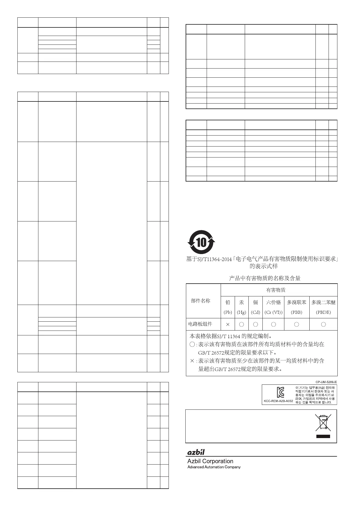
Disposal of Electrical and Electronic Equipment (for Environmental Protection)
This is an industrial product subject to the WEEE Directive.
Do not dispose of electrical and electronic equipment in the same way as household waste.
Old products contain valuable raw materials and must be returned to an authorized
collection point for correct disposal or recycling.
 Loading...


