AB-6256
5
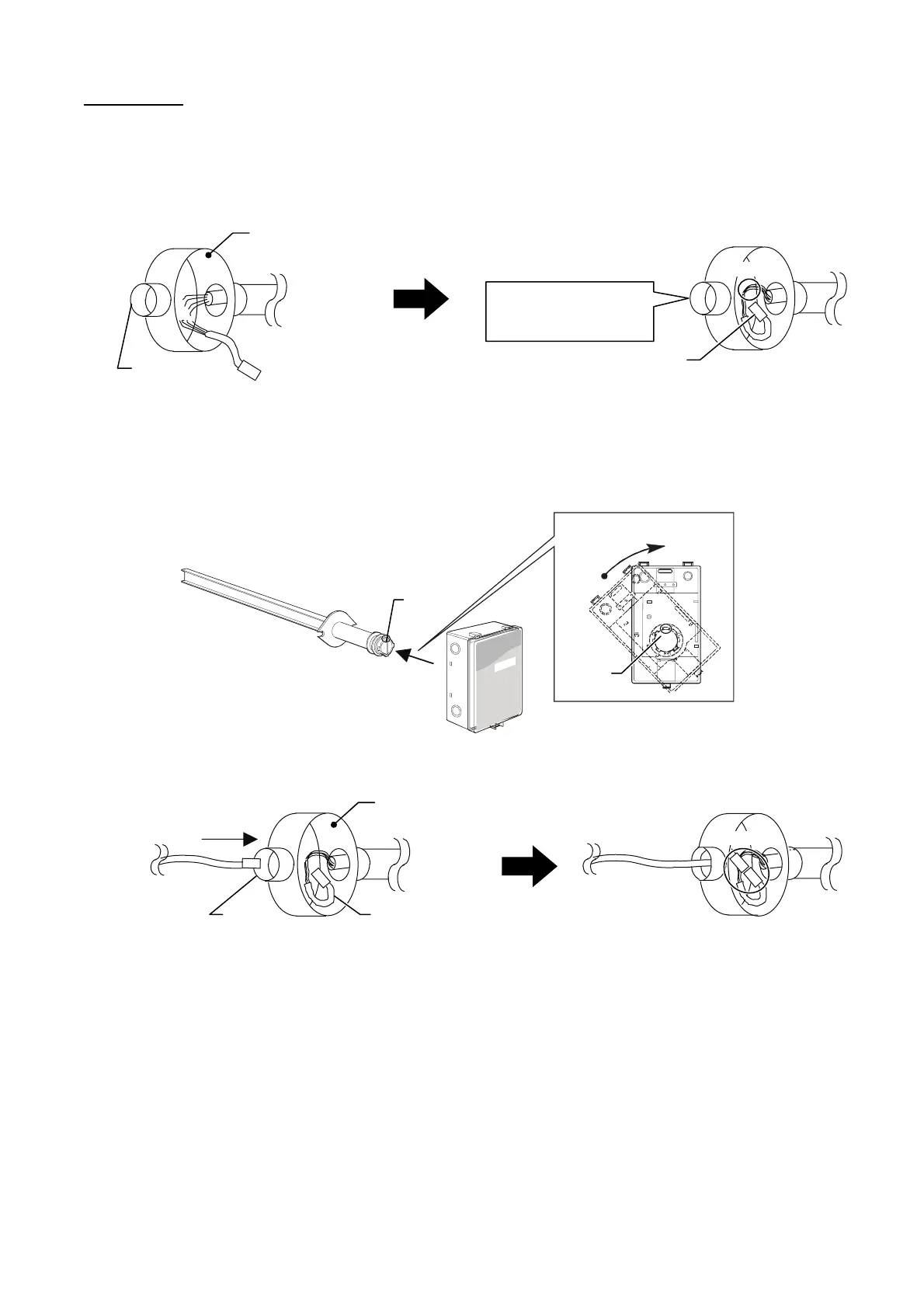
Cable assembly: Following is an example of cable assembly installation using round outlet box (JIS* C8340) with two entries.
∗ JIS: Japanese Industrial Standard
Lead the controller cable into the outlet box through an entry. Connect the controller cable with the cable assembly, as shown in
Fig. 4.
Note that the size of the entry must be large enough for the main unit cable connector to lead through. The main unit cable will
be connected when the power is supplied. (See Figs. 1 and 4.)
Figure 4. Connection example of cable assembly
Installation of main unit
Main unit is easily assembled with the sampling probe by snap-in bayonet mount. Refer to the following procedure.
1) Engage the notches of the main unit with the locking knobs of the sampling probe, then lightly press the main unit.
2) Turn the main unit clockwise until it stops, as shown in Fig. 5.
Figure 5. Assembling the main unit with the sampling probe
3) Connect the main unit cable with the cable assembly, to which the controller cable has already been connected, as shown
in Fig. 6.
Figure 6. Connection of the main unit cable with the cable assembly
Round outlet box
with 2 entries
Controller
Cable assembly
Entry
Lead the main unit cable
through this entry to connect
with the cable assembly.
Cable assembly
Connect.
ssemble.
ttach.
Turn.
Notch
Locking
knob
Controller
Main unit
Round outlet box
with 2 entries
Lead through entry.
Entry
Cable assembly
Connect.

 Loading...


