AB-6256
6
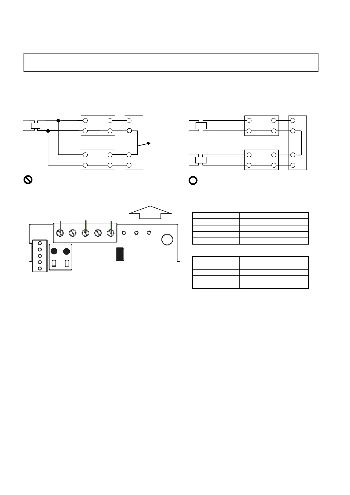
Wires Connection
Connection of power supply line
IMPORTANT:
Do not apply power supply voltage other than 24 V AC. Otherwise, it may damage the product.
Use insulation transformer. Do not share the 24 V AC power supply with any other device. If the transformer is shared, a loop
will formed at common and the product may get damaged. Refer to the following examples.
Shared transformer: Incorrect example
Separate transformer: Correct example
Loop is formed at the common line. Loop is not formed at the common line.
Figure 7. Connection examples: with shared transformer and with separate transformers
Terminals layout
Figure 8. Terminals arrangement
Operation
Operation check
Remove the front cover of the main unit, and breathe directly onto it 10 cm away from the main unit. Check that the reading on
the LCD and the output ascend quickly.
LCD indication
On the LCD, CO
2
concentration is continuously displayed. The display is changed a when a button is pressed, as shown in Fig.
10. For the layout of each button, see Fig. 9.
In the event of equipment trouble, tool icon is displayed on the LCD, as shown in Fig. 11.
LED indication
Green LED: Normal operation
Yellow LED: Initializing, pressing a button, error during calibration
+
∼
⊥
24 V AC
Multi-loop
controller
CO
2
concentration
transmitter
Shared
common line
CO
2
concentration
transmitter
- ⊥
+
+
∼
+
⊥
-
⊥
24 V AC
Multi-loop
controller
24 V AC
+
∼
+
⊥
-
⊥
+
∼
+
⊥
-
⊥
UP
BR WH Y GR
Lead wires of the main unit cable
Lead color Description
WH: White 24 V AC power (common)
BR: Brown 24 V AC power
GR: Green Common output (-)
Y: Yellow 1-5 V DC output (+)
Lead wires of the cable assembly
Lead color Description
White 24 V AC power (common)
Brown 24 V AC power
Green Common output (-)
Yellow 1-5 V DC output (+)

 Loading...


