Valve Positioner Azbil Corporation
4-2 Model VFR - FloWing Eccentric Rotary type Control Valves
Installation
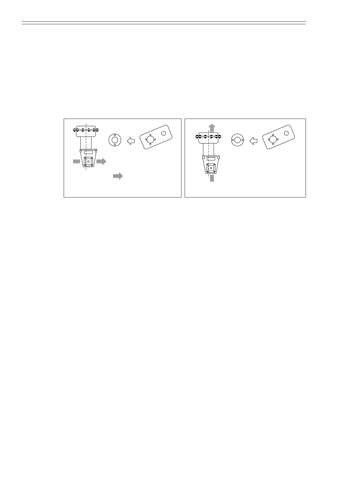
(1) Install the spacer onto the bracket.
(2) Install the connector-plate onto bracket with feedback-pin. Since the position of
spacer’s pin changes by ow direction, attach with reference to Figure 4-2 and
Figure 4-3.
(3) Tighten the clamping-bolt (M10, hex-hole-head) and attach the indicator to the
connector-plate, and then tighten the clamping-bolt (M12, hex-hole head) and
attach the pointer and mounting-plate.
(4) Connecting the air piping.
Figure 4-2 Figure 4-3
4-1-3 : Adjusting the positioner
For details on positioners, refer to the respective manuals listed below.
CM2-AVP300-2001
CM2-AVP303-2001
}
for SVP
4-1-4 : Maintaining the positioner
For details on positioners, refer to the respective manuals listed below.
CM2-AVP300-2001
CM2-AVP303-2001
}
for SVP
4-1-5 : Troubleshooting
For details on positioners, refer to the respective manuals listed below.
CM2-AVP300-2001
CM2-AVP303-2001
}
for SVP