Valve Positioner Azbil Corporation
4-10 Model VFR - FloWing Eccentric Rotary type Control Valves
4-2-6 : Adjusting the positioner
The positioner installed on a valve has been factory adjusted before shipment. When
it has been replaced, however, the newly installed positioner is required to be adjusted
in the following procedure.
(1) Switch the bypass cock to “ON”.
(2) Conrm the positioner input air pressure range, supply air pressure and actuator
spring range by referring to the nameplate.
(3) Feed the supply air to the posiitoner.
(4) The procedures hereunder are divided into steps for a direct-action positioner and
those for a reverse-action positioner, and assume an input air pressure range of
20-98 kPa{0.2-1.0 kg/cm²} for both cases.
*1: If the input air pressure range of the positioner is 20-60 kPa{0.2-0.6 kg/cm²},
substitute 98 kPa {1.0 kg/cm²} with 60 kPa {0.6 kg/cm²} and 20 kPa {0.2 kg/
cm²} with 60 kPa {0.6 kg/cm²} in the following steps.
For direct action positioner (air-to-open)
(5) Set the input air pressure to 20 kPa {0.2 kg/cm²}.
(6) Turn the zero adjustment knob so that the output pressure of the positioner
becomes the lower limit of the actuator spring range. When this is done, the
indicator will indicate “S”.
(Example: If the spring range of the actuator is 98 - 200 kPa {1 - 2 kg/cm²}, set
the output pressure of the positioner to 98 kPa {1 kg/cm²}.)
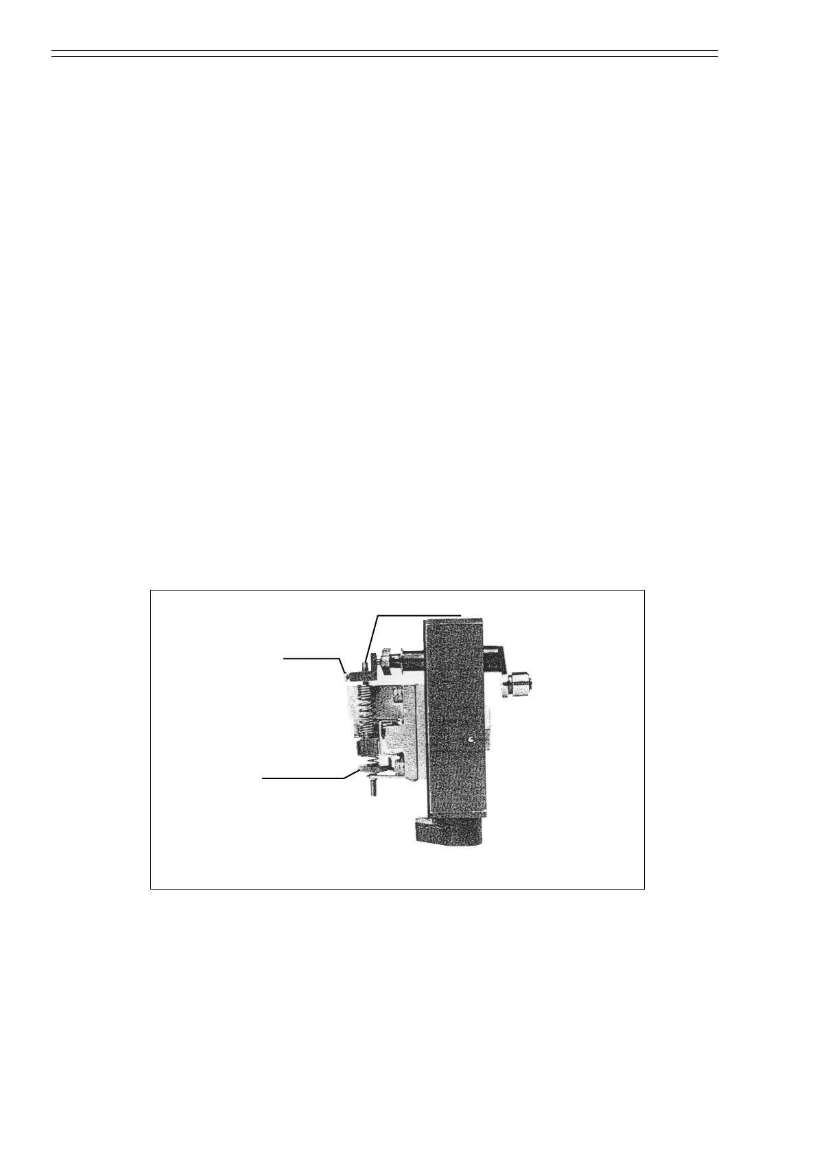
Lock screw
Figure 4-19 Adjusting the positioner
(7) Set the input air pressure to 98 kPa {1.0 kg/cm²}.
(8) Loosen the lock screw with a screwdriver (-) and adjust the SPAN control so that
the indicator indicates “0”.
For direct action positioner (air-to-close)
(5) Set the input air pressure to 98 kPa {1.0 kg/cm²}.