Azbil Corporation Valve Positioner
Model VFR - FloWing Eccentric Rotary type Control Valves 4-9
(e) Release the air pressure applied to the actuator and disconnect the air piping.
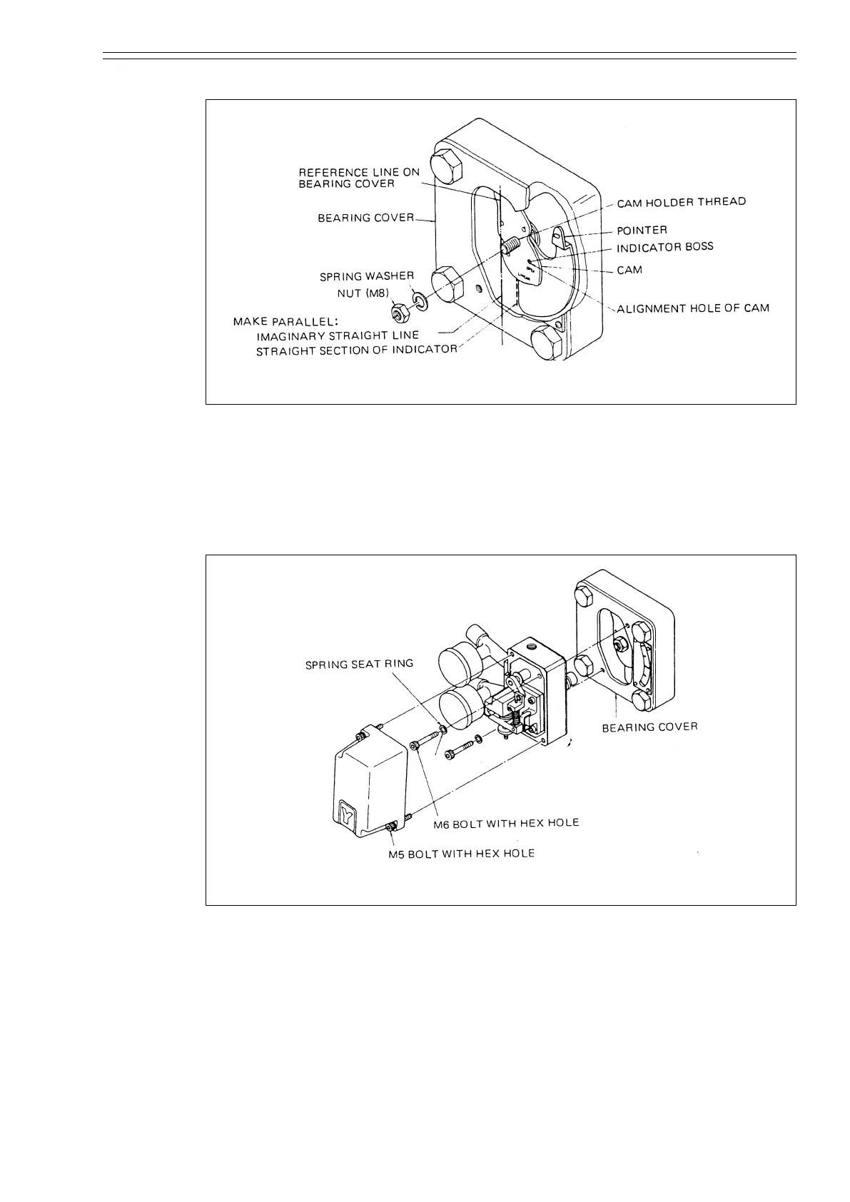
Figure 4-17 Installation of indicator and cam (for direct action and linear characteristics)
(3) Installing the positioner
(a) Loosen the two clamping-bolts (M5, hex-hole head) with a hex wrench (4
mm) and remove the positioner cover.
(b) Mount the positioner (in such an attitude that the bypass cock is points
downward) on the bearing cover with two bolts (M6, hex-hole head) and
spring washers using a hex wrench (5 mm).
Figure 4-18 Installation of positioner
(4) Connecting the air piping
Proud air piping between the union joint and the three air connection ports (IN,
SUP, OUT; PT l/4 tap thread) on the side plate of the positioner.
IN : Input pneumatic pressure from controller
SUP : Air supply
OUT : Output pneumatic pressure to actuator
~Note
Apply liquid packing to the threaded sections of the connectors. Do not use
seal tape lest air paths of the positioner should become clogged.